CLEMENTS CORNER
Tom has logged over 23,000 flight hours, is a Gold Seal CFI, and has type ratings in the Learjet,
Douglas DC-3, BE-300, and BE-1900. He has written numerous articles for “King Air,” “Twin
& Turbine,” and “Kilo Alpha” magazines. In the 1970s, Tom served as the Training Center
manager for Beech Aircraft Corporation. He subsequently went on to form a successful training
organization, Flight Review, Inc., and wrote The King Air Book Volumes I & Two, considered by many pilots and
aviation industry professionals to be the premier manuals on King Air operating techniques.
Whoa, Not So Fast! (Yaw Damper)
When do you turn on the Yaw Damper after takeoff in your King Air 200? I observe many pilots make this the second step of their after takeoff flow pattern: Gear up; Yaw Damp on. I want to convince you to make it the fourth step.
I teach the use of what I call “The Y Pattern” after liftoff. This pattern gets its name from the location of the controls or switches being touched. The first step, the upper right extreme of the Y, is to raise the landing gear handle. The second step, the upper left portion of the Y, is to turn off the landing and taxi lights. (They do not shut off automatically and the nose wheel well can get very hot resultant decreased bulb life if they remain on too long.) The third step is to reach to the center of this rather poorly-shaped Y and retract the flaps.
Yes, yes, I realize that many if not most pilots tend to takeoff with no flaps, especially on longer runways…and that is as it should be. However, when the runway length is limited, the charts often prove that more payload may be safely carried by use of Approach flaps. Since we use the flaps somewhat rarely, it is very, very, easy to overlook their being extended and to climb out to or well past pattern altitude before recognizing our mistake. Oops! So that is why I encourage you to always check the flap handle as the third after takeoff step, even though you may need to move it to the Up position only once in a blue moon.
Step Four? Finally, we reach to the bottom of our little Y and activate the Yaw Damper.
“But, Tom, that’s too late! I don’t want my passengers to be subjected to un-damped yaw that long!” I agree that passenger comfort is a wonderful goal…but never at the expense of passenger (and pilot!) safety. Let me explain.
First, I am not talking about a lengthy delay. Since the POH procedures call for flap retraction at 400 feet HAA (Height Above Airport) after accelerating to VYSE, that’s the attitude I suggest you use for Yaw Damper activation. So, at the most, we are talking about thirty seconds or so after liftoff before we get the increased ride comfort provided by the YD.
Second, is the Yaw Damper so much better in damping yaw than your own feet? For some, sadly, the answer will be a resounding, “Yes!” Others, perhaps more experienced and with a tailwheel endorsement, will realize that aggressive and proper rudder control can do nearly as good a job of damping yaw than the electronic marvel. (But it does get tiring, so the Yaw Damper is certainly welcome, at or above 400 feet!)
So where is the safety issue I mentioned? It is this: Having the Yaw Damper on makes aircraft heading control and inoperative engine identification more difficult.
Realize that the YD only helps to prevent yaw. It does not, unlike Rudder Boost, help apply force to the necessary pedal. I am sure you’ve tried moving the rudder pedals with the Yaw Damper on, right? What did you feel? A typical response is “The pedals felt like they were in concrete!” Yep, they are certainly stiff and unresponsive when the Yaw Damper is engaged…and that makes keeping the nose straight following a low altitude engine failure just that much more difficult. Also, when it comes to “Dead Foot, Dead Engine,” the Yaw Damper makes it more difficult to positively and immediately differentiate the active from the inactive foot.
That is why Yaw Damper activation should be relegated to its proper position as step four after lift Save & Exit off, not before. Please don’t rush it.
Prop Sync Types (which do you have?)
How can you tell if your King Air has the older Type I or the newer Type II Propeller Synchrophaser system? There are two ways to tell from the cockpit.
First, does the label by the Prop Sync switch merely say “On-Off” or does it also have the statement “Must Be Off for Takeoff and Landing?” If you have the former, you have Type II. If you have the extra comment of the latter, it’s Type I.
The second way to tell involves turning the battery switch on. When you turn on the Prop Sync switch here, on the ground with the gear handle down – I sure hope so! – do you get a yellow “Prop Sync ON” annunciator? Yes? Then you have Type I. No? Then it’s Type II. Type I uses an electromechanical device on the right engine that can make minor adjustments to the governor attachment end of the propeller cable. It can make the cable longer to slightly increase the governor’s speed setting or shorter to decrease the speed setting in an attempt to make the right propeller speed match the left. The range is quite small, about 30 RPM total, or 15 RPM from neutral. Although limit switches inside the assembly should stop the motor and prevent any harm when and if the device drives the adjustment mechanism to an extreme, it is not uncommon to find that in fact, the mechanism binds up or jams when an extreme travel limit is reached.
The pilot has two ways of telling that his sync motor has jammed. First, the dang system is inop. Unless the propeller levers are carefully adjusted by the pilot, the disconcerting whaa-whaa sound of out-of-sync propellers is heard. Second, there now appears a significant misalignment, or stagger, between the left and right propeller knobs in the cockpit.
If the right knob is well behind the left, then the sync motor has probably jammed in the “Increase RPM” position, making the cable longer and requiring the knob in the cockpit to be further back to compensate for the longer cable. Vice versa, if the right knob is forward, the likelihood is that the mechanism is jammed in the “Decrease RPM,” or short, position.
Luckily, it is usually fairly easy for maintenance personnel to access the assembly, get it back to neutral, and adjust the limit switches as needed.
This tendency to jam when reaching a limit is why the extra panel statement – Must be Off for Takeoff and Landing – is a required placard. Whenever the combination of power and airspeed are both sufficiently low such that the propellers are not yet on their governors, there is no way that they will always have their speeds perfectly matched. This will certainly occur during the early stages of the takeoff roll and during the flare and rollout stages of the landing. If sync is on now, the poor mechanism will assuredly be driven to a limit. In fact, as the pilot or the wind gusts cause some speed fluctuations, there is an excellent chance that the mechanism will be driven back and forth from one extreme to the other…just asking for a problem.
Although the placard only speaks of takeoffs and landings, the switch should always be off whenever there is a reasonable chance that the propellers will not be at or near the identical speed. Doing slow flight and stall practice, during any simulated or actual single-engine maneuvering…make sure the switch is off. When you fly a King Air for the first time, you should have the switch off when moving the propeller levers from takeoff to climb speed and from climb, speed to cruise speed. This allows you to find and know what, if any, propeller lever stagger is required in this particular airplane to set the governors at the same speed. Since the adjustment range of the sync system is small, you need to make sure the propeller speeds are very close together before using sync. However, once you know, for example, that the left knob needs to trail the right knob by 1/8 of an inch, then it is perfectly acceptable to leave sync on when changing RPM.
Type II, on the other hand, does not have a slave (right) unit attempting to follow a master (left) unit. Instead, the slower always tries to rise to the faster speed, but again in a very limited range. Furthermore, and more important, there is no electromechanical mechanism to bind up or jam! Instead, speed adjustments are made by varying the strength of a magnetic field inside the governor itself. Cool! Since there is no worry about the mechanism binding, we can leave it on all the time even when the propellers are not on the governors, not in sync.
However, even Type II has its potential problems, although minor.
First, the darn thing seems to go nuts every so often. There you are in steady-state cruise and suddenly the props go well out-of-sync. What the heck?! Turn off the sync switch, sync the propellers manually, and then turn the switch back on. You will find in almost every case that the system goes back to being its usually obedient self. If this happens once or twice every few flights, you will just learn to live with it because no problem will be found when troubleshooting takes place. Only if it becomes a continuous bother on nearly every flight should you spend money having the mechanic find and fix the problem.
The second problem with Type II appears rarely and is more common on the 300-series than the 90- and 200-series. When nearing the runway for landing – or when slowing toward a stall during flight training – once in a great while you will feel and hear the airplane start doing a rhythmic left-and-right yawing “dance.” When you examine the engine instruments, you will probably notice that torque and propeller speed is fluctuating.
The cause of this is a battle between the two governors as the propellers just start slowing off of the selected speed. One side may drop a little speed first and so the sync system speeds it up. Now the other side is slow, so it gets boosted up. A little battle ensues, with each side increasing then easing its governor’s speed setting…leading to the yawing dance you are feeling. Solution? Turn the sync switch off and – Voila! – things immediately smooth out as they should.
I hope this provides some interesting and important details about this little system that contributes its share to passenger comfort.
Flaps – Infinitely Selectable?
If you are used to flying one particular King Air but then get the opportunity to fly others, you will find a surprise or two…and one of these relates to flap operation. All current-production King Airs have three-position flap systems. Where you place the flap handle is where the flaps should go and stop: Up, Approach, or Down. It is simple and easy. About the only concern is to abide by the flap limit speeds – and I prefer being 20 knots or so conservatively under the limits, when practicable – and verify that the flap indicator shows you what you expect.
Earlier model King Airs, however, have a flap system that is greatly different in the Approach to Down realm. When the flap handle on these models is placed to the center, Approach, position, what happens depends on whether you have come to the center position from the Up or from the Down position. Let me explain.
In these models, moving to Approach from Up yields the identical action as in the later models: the flaps move to Approach and stop. Coming up to Approach from Down, however, causes the flaps to stop right where they are.
If you have set 100% flaps for a normal landing but then must do a go-around, here’s an opportunity to use your Four Friends: Power, Props, Flaps, and Gear. You push the power levers forward aggressively, stopping at your normal takeoff torque or ITT setting. Next, you smoothly run the propeller levers fully forward. Since this causes the torque to drop appreciably, don’t be timid about using the full torque limit when you pushed the power levers forward, if ITT is not limiting Now it’s time to retract the flaps, and here’s where a big gotcha awaits those of you used to the newer three-position system.
If we move the flap handle up one notch, from Down to Approach, nothing happens! As I wrote above, “Coming up to Approach from Down causes the flaps to stop right where they are.” When we next retract the landing gear, the gear warning horn starts to sound (on most models), triggered by the fact that the flaps are extended greater than Approach without all three gear legs down and locked. So we have a blaring horn and a poorly-performing airplane since the flaps are still fully down. Yuck!
On these earlier models, the way to retract the flaps to Approach from Down is complicated enough that I do not recommend the single-pilot operator to do so. Instead, merely delay flap retraction a moment longer, to make certain that you are comfortably in the green arc on the airspeed indicator, then bring the flaps all the way up in one step by moving the flap handle to Up. Even for the two-pilot crew, this is a good option.
But if the two-pilot crew wants to do the “optimum” procedure, performance-wise, then power and props come first and second, flaps to Approach comes third, gear retraction comes forth, and then final flap retraction takes place last after 400 feet and Vyse are both achieved.
To get the flaps from Down to Approach, the copilot must move the handle fully to Up, watch the flap indicator, and exactly as the flaps reach the Approach setting he/she must then move the handle down one notch to Approach.
If the copilot does this too fast and returns to Approach when the flaps are a bit greater than Approach, they stop right there. This leads once again to the blaring gear horn when the gear starts coming up. On the other hand, if the copilot is too late and the flaps have reached a setting between Up and Approach when the handle returns to the center, then the flaps immediately reverse direction, move down to Approach, and automatically stop there. This does not harm the flap system in any way.
Due to the complications and potential for errors in this procedure, I prefer to make a one-step, Down to Up, flap retraction even when operating with a copilot.
On the other hand, there is one distinct advantage to the earlier-style system. Since the flaps are infinitely selectable at any position from Approach to Down, we can use a third or even a fourth flap setting when landing in visual conditions. We could stop the flaps at, say 60%, when on base leg, and then perhaps at 80% when rolling out on final, and finally going to 100% at 500 feet above touchdown. This is done by moving the handle from Approach to Down, watching the indicator, and returning to the center position when the indicator shows what we desire. Due to the dynamic braking system that the flaps have, there is no need to anticipate and move the handle back to Approach early. Some people, including me, like to use that 60% setting momentarily – it leads to less trim and pitch changes taking place all at once – but others find it more work than necessary. To each his own!
There is, however, one definite benefit of making an intermediate flap stop between Approach and Down: It forces you to watch the indicator. Remember, people, controls are not indicators. Just because the flap handle or gear handle gets repositioned, that is absolutely no guarantee that the expected action actually occurred. Flap indicator, a visual check outside, green gear lights, red lights in the gear handle…all of these are the things that confirm what is actually happening.
I’d be a richer man today if I had a dollar for every time during my years of active King Air flight training that the trainee missed the fact that the flaps and/or landing gear did not do what he or she expected. (Damn those instructor’s fingers having access to circuit breakers!) Taxiing back for takeoff after many a full-stop landing, my line was, “Well, I have good news and bad news. The good news is that you make a reasonably good no-flap landing. The bad news is that you did not realize you were making a no-flap landing!”
To close, the easiest way to know for sure which style flap system your particular King Air has is to run the flaps fully Down once before your first takeoff in this particular serial number, move the flap handle back up one notch to Approach, and observe whether they return to Approach or stay Down. If they come back to Approach, you, of course, have the newer three-position system. For those readers who want to know now, the newer system is on all C90Bs and after (not C90As), all 350s, and all 200-series after BB-1443, including B200GTs and 250s. That means that all 90s, A90s, B90s, C90s, C90-1s, E90s, F90s, F90-1s, 100s, A100s, B100s, straight 200s, 300s, and B200s prior to the 1993 year model all have infinitely selectable flaps in the range from Approach to Down. That’s a lot of airplanes!
King Air Indicators vs Controls
In last month’s Clements Corner we mentioned how important it was to use the flap indicator to verify that the selected flap position actually was achieved. I wrote:
‘There is, however, one definite benefit of making an intermediate flap stop between Approach and Down: It forces you to watch the indicator. Remember, people, controls are not indicators. Just because the flap handle or gear handle gets repositioned, that is absolutely no guarantee that the expected action actually occurred. Flap indicator, a visual check outside, green gear lights, red lights in the gear handle…all of these are the things that confirm what is actually happening.”
All I want to do in this month’s column is to emphasize the simple observation that controls are not indicators.
There is a ridiculously simple technique that will guarantee that you properly observe the Indicator. It will prevent you from falling into the trap of assuming that because a Control was moved, the expected result actually occurred. I am surprised that more pilots have not been taught this technique since it is so easy and foolproof.
It is merely this: Never take your hand off of the Control until the Indicator verifies the expected result.
Because a gear up landing is such a common and expensive mistake, an extension of the landing gear may be the most critical situation in which this technique should be used. When you, or the copilot, place the gear handle in the down position, keep touching it. The red handle lights will, of course, illuminate as the gear begins to move and the red lights will extinguish just as the third green gear down light illuminates. Now, probably accompanied by a “Three green, no red” statement, take your hand off the handle and proceed to the next step of the landing procedure.
I have received only two arguments against this technique over the years. One is that it is somewhat awkward to hold the handle when it on the other side of the power quadrant, as it is in earlier King Air models. Yes, true. But I think the momentary awkwardness is justified by the benefits of the technique. The other negative argument is that it takes too much time, that we need to be using that hand for other things now. Really? Really?! If you don’t have six seconds or so to leave your hand there, then you are rushing much too fast through the cockpit tasks. You need to work at slowing down and being more deliberate.
By using this technique, you will find the occasional surprise immediately, while there is more time to think, analyze, troubleshoot, and correct. For example, if the red handle lights extinguished but only two green lights illuminated, we immediately know there is a problem, but probably merely a bad switch or bulb. We know that the red lights should not go out until all three gear downlock switches are activated, so the likelihood of one gear not being down and locked is highly improbable. Isn’t it better to find this discrepancy at glideslope intercept or on a visual downwind leg, rather than when making a gear check on short final?
We have already discussed in the previous article about keeping your hand on the flap handle until the flap indicator confirms the proper position. It’s a no-brainer.
Here are some additional steps in which this technique may and should be used: (1) Windshield Heat activation. After your eyes have helped your fingers locate the proper switch, don’t move it until the eyes move to the electrical load meters. Make sure you see a slight increase as the switch is moved. (2) Prop Heat switch. Same thing. Don’t take your fingers off the switch until the propeller ammeter is checked for being in the green arc showing proper amperage. (3) Deice boots. As you tap the switch to single-cycle, observing the boots themselves on the wings’ leading edges as well as seeing the expected drop and recovery on the Pneumatic Pressure gauge shows you things are AOK.
It almost goes without saying that movement of the power quadrant controls should be verified by engine instrument changes. Yes, I guess the kick in the seat of your pants is enough to know that power has actually increased when the power levers were pushed further forward, but since King Airs have no automatic temperature or torque limiters, we need to be watching the gauges, too.
A great King Air salesman, pilot, and friend – Rod Rodriquez of Beechcraft West in Van Nuys, California – was the mentor who taught me this very technique back in 1972. Thank you, Rod! It has served me – and others – very well.
Pressurization: Setting the Controller vs. Verifying the Results
The typical Normal Procedures King Air checklist addresses Pressurization four times. Before I discuss them, give yourself a pop quiz: Can you state in what ground or flight phase the “Pressurization” Challenge is listed and what your Response should be in each case? Take your time; I’ll wait.
Ready to compare your answers to mine? The first reference is in the Before Takeoff phase, in which you are directed to set the pressurization controller for the proper cabin altitude based on our anticipated flight. The second reference is in the After Takeoff (sometimes labeled Climb) phase, where there is a rather cryptic “Pressurization – CHECK” listed. The third mention is in the Descent phase, where we set the controller for landing. (I usually do this as the last step in the Cruise procedure, as discussed in my book.) Finally, the fourth mention – again, that overly-simple “Pressurization – CHECK” statement – appears in the Before Landing phase.
If you have been reading these monthly ramblings in order, you know that my blurb last month emphasized the difference between Controls and Indicators…that just because a flap switch gets moved, there is no guarantee that the flaps actually went to the position you were expecting. The technique I preached was to never let go of the control until the indicator shows visual confirmation of the status.
This technique does not work with the pressurization controller since it would require much of our climbs and descents to be one-handed, while we kept the other hand on the controller! However, the idea is the same: Just because we dial a certain cabin altitude and climb or descent rate into the pressurization controller, that control operation provides absolutely zero guarantees that the cabin will be doing what it should.
Here’s what those two “Pressurization – CHECK” checklist steps actually mean. I observe too many pilots responding to that step by looking at the controller to verify that it is set properly. No! You’ve already done that. Instead, your eyes need to be directed at the two pressurization indicators, the cabin’s Vertical Velocity Indicator and the combined cabin Altitude and Differential Pressure gauge!
There are lots of reasons why the pressurization system may not be working properly. Bleed air may not be turned on, the control switch may be in Dump, the airplane has so many air leaks that it is a flying sieve, your power setting in the descent is too low, the Pre-set solenoid is not working…these are some potential reasons why the expected result is not taking place.
For the “Pressurization – CHECK” step that occurs after takeoff, I suggest your first observation should be of the Differential Pressure gauge’s needle since if it is at zero you’re nor pressurizing at all. Because the pressurization controller is merely a governor for cabin altitude, the second observation should be of the cabin Altitude needle. It either needs to be already pointing to the altitude that you dialed into the controller or on its way up or down to get there. Lastly, if the cabin is now changing its altitude, observe the climb or descent rate and adjust the Rate knob as necessary.
For the “Pressurization – CHECK” step that occurs before landing, verify that the cabin Altitude needle is pointing close to the landing field’s elevation, in accordance with what you’d dialed into the controller when or before the descent began. Also, knowing that a 1 psid Differential Pressure value, at low altitudes, means that the cabin is about 2,000 feet below the airplane, if you are coming up on the Outer Marker or traffic pattern altitude, you need to be seeing less than 0.5 psid.
It is very embarrassing to decide to divert to Flagstaff with the controller still set for your originally-intended landing site of Phoenix. Unless you observe that the cabin is about 6,000 feet lower than Flagstaff and correct it promptly, you’re going to give your passengers a sinus-clearing experience at touchdown!
Magic Numbers...Approach Power Settings That Work!
I like to make things as easy as possible when I fly. At the factory’s Beechcraft Training Center in Wichita back in the ’70s, we taught the use of what we called “Magic Numbers” that applied when operating in the instrument approach environment. Lord knows, there is enough going on during that busy and critical time that not having to spend much thought or effort on setting engine power is a useful simplifier.
The various King Air training providers of today have, often, continued to present these useful Magic Numbers. However, some King Air pilots have never heard of them! Consequently, they make their approach phase of flying a bit more stressful and less accurate than it needs to be. Before I present the table with the power settings, I need to spend a little time defining what the various instrument approach phases mean and discussing their significance. Here goes: Read the entire article
The C90 Crossfeed Trap
Well, actually it’s the A90, B90, C90, C90-1, C90A, C90B, C90GT, C90GTi, and C90GTx trap…and it’s a big one.
I devoted an entire chapter of The King Air Book to the C90-type fuel system and if you operate one of the above models and haven’t done so already, please read and study that chapter carefully. One of the things discussed therein is a couple of suggestions about when leaving the Crossfeed switch in its center, Auto, position is not the best idea.
Since that chapter was written, however, I have become convinced that using the Auto position for routine operation is counterproductive to safety. It has caused a few one-engine and even two-engine fuel starvation incidents which did not need to happen, and I cannot estimate how many close calls have taken place that will never be documented. Read on to understand what’s happening.
A quick review: The purpose of a boost pump on the PT6 is to prevent cavitation of the engine-driven high-pressure fuel pump…the only pump that can supply the fuel that the engine needs for operation. If that high-pressure pump ever decides to call it quits, you’ve lost the engine. The boost pump cannot keep the engine running, unlike the situation in a lot of piston aircraft engines. All King Air models not listed in our long list above have two boost pumps per side, either two electrically-driven ones (Straight 90, Straight 100) or an engine-driven one and an electrically-driven one (all others). If one boost pump quits on these models, a standby pump is waiting to do the cavitation prevention.
That’s not the case, however, in the C90 group. In these King Airs, there is an electrically-driven boost pump per side, only, no standby. Thus, the designers thought it would be a clever idea to automatically open the crossfeed valve in the event of a boost pump failure. This would allow the opposite side’s pump to provide the standby, cavitation-preventing, function.
To do that, however, means that the remaining operative boost pump is now feeding fuel to both left and right high-pressure pumps. In other words, we have totally lost the fuel on the side of the dead pump. Presuming the fuel load was balanced initially, we now have half the fuel we had a moment ago before the pump quit.
In the cockpit, our indication of this will be the unexpected illumination of the yellow “Crossfeed” annunciator light. Unless we had been staring at the annunciator panel just as the pump quit, we would not have seen the momentary illumination of the left or right red “Fuel Pressure” annunciator. This light came on when pressure dropped below 10 psi but that pressure drop is also what triggered the crossfeed valve to open, restoring the pressure and thereby extinguishing the light.
So, typically, all the pilot will observe is an annunciation that the crossfeed opened. Is there a checklist procedure to follow now? Of course! Can we get the other half of our fuel back in use if we need it? Of course! But, dang it, too many pilots have merely shrugged their shoulders and done nothing, perhaps lulled into complacency due to the yellow nature of the light.
And then what happens? Both engines keep running perfectly as they consume fuel from the same side. After enough time, it is easy to see that one side’s fuel quantity gauge is not going down at all while the other side’s gauge is dropping twice as fast as normal. Folks, you need to be checking those gauges every now and then, at least a couple of times every hour! By not doing so, how will a major fuel tank leak be discovered? And in this case, how will we know that a boost pump failure was the triggering mechanism for this unexpected use of crossfeed?
So although it 100% should not have happened, more than one operator did not notice a problem until the feeding tank hit zero and both engines quit within moments of each other! I hate it when that happens! Air-starts will be unsuccessful since it is easier for each engine to suck the air out of the empty side rather than sucking fuel out of the other side.
If this asleep-at-the-wheel pilot finally recognized the problem and moved the crossfeed switch to the Closed position, at least now the engine on the side with the fuel would be capable of air-starting and running just fine…with the Fuel Pressure annunciator illuminated indicating that cavitation is taking place.
Not as bad as the double engine failure, is the single engine failure that again follows improper knowledge and operation of Auto crossfeed. Unlike our totally asleep-at-the-wheel dummy in the previous case, this only half-asleep pilot did finally check his fuel gauges and (1) realized that one side was dangerously low while the other side was fine, (2) got out the checklist, (3) followed the checklist by moving the crossfeed switch from Auto to Closed, and (4) began feeding the high side’s fuel to that side’s engine.
The bad news here is that, without the boost pump on the high fuel side, we cannot feed that fuel to the opposite engine, the one on the side that’s getting dangerously low. If we cannot land before that low fuel is all consumed, we lose that side’s engine. The good news is that at least we have one engine operating perfectly, but with its Fuel Pressure annunciator illuminated, reminding us that we are cavitating the high-pressure pump.
Quiz time: What is the time limit on cavitation? Ten hours! Geez, that’s a long time. You’ll never log anything even close to that amount as you complete this single flight, right?!
In reality, neither one of these engine-failure scenarios should ever have happened following a boost pump failure. A competent, knowledgeable, pilot would have immediately moved the crossfeed switch to Closed in response to the Crossfeed annunciator’s illumination. Doing so will cause one side’s Fuel Pressure warning light to come on, so now the pilot knows exactly which pump died. More importantly, he can now examine his fuel status and decide if half the current fuel is sufficient, with a safety margin, to complete this leg. If so, then he can move the switch up to Open – the Auto position would also work – and not have to record any cavitation time except for the few moments he operated with the crossfeed switch Closed.
On the other hand, if this pilot’s analysis of the fuel situation leaves him or her with even a shadow of a doubt that half of the current fuel will not be enough to safely complete the leg, then he can leave the crossfeed switch closed, keep the fuel balanced and totally consumable, and merely record a little cavitation time, the time remaining on this leg.
(The C90B and after models have the ridiculously low fuel imbalance limit of 200 pounds! The previous models have no imbalance limitation whatsoever. So you pilots of C90Bs and the C90GT-series, if you lose a boost pump while operating with the crossfeed switch in Auto, within thirty minutes or so you’ll be in violation of that silly limit.)
I have concluded, based on the above discussion, that there should not be an Auto crossfeed switch position. Instead, a two-position, Open and Closed switch is all we need. Leave it closed for all normal operation. If and when a boost pump dies, you will already be at the first step our “competent, knowledgeable” pilot took. You will immediately know which side lost pressure and now you can analyze and decide whether to record cavitation time – the better choice in many situations and virtually mandatory for the C90B and after crowd to keep the fuel balanced – or whether to crossfeed, prevent cavitation and lose half your fuel.
“But, Tom, isn’t there a time when the boost pump is necessary for engine operation? Didn’t I read somewhere about how a boost pump was necessary above 8,000 feet?”
Two things you are recalling: First, using gasoline, not Jet fuel, boost pumps are required above 8,000 feet due to the extra volatility of the gas. There may be enough vaporization caused by the sucking action of the high-pressure pump that fuel flow and power fluctuations will occur. Second, very hot Jet fuel at a high enough altitude may have enough volatility to experience the same effects.
So with gasoline onboard – for most of us, something we never have done or will ever experience – use the Auto position above 8,000 feet. And if you depart Yuma, Arizona, one August afternoon after sitting all day in the heat, climb directly to FL250, then lose a boost pump soon after leveling off, you may experience some fuel flow and power fluctuations until you (1) open crossfeed, or (2) reduce power (since the slower speed of the N1-driven pump will cause less sucking action), or (3) descend into thicker, higher-pressure air.
As you can see, in my opinion, there are almost no situations in which the crossfeed valve remaining closed, while we analyze a boost pump failure scenario, will ever cause a problem.
Two closing comments: First, Beech has not modified their POM/POH procedures and has not endorsed my recommendation. I would not, of course, be making this recommendation if I thought it was harmful to the airplane or to us. If you choose to follow my recommendation, do so with the knowledge that it is an officially unapproved procedure. Second, it would be so easy to add an engine-driven boost pump on the C90 group, just as in most other King Air models, that I am amazed a Raisbeck or a Blackhawk or some other modifier has never offered this as an upgrade. Heck, the drive pad on the engine’s accessory case is already there, but covered by a plate. Come on, somebody, bring the C90 fuel system into the modern age and totally eliminate Auto crossfeed! Please!
Landing Approach Speed
In the POH’s Landing Distance charts there is a table that lists “Approach Speed” as a function of landing weight. The heavier the weight, the faster the speed. Since the landing comes at the end of the approach, some pilots, understandably, are unsure as to exactly what this speed is and when it applies. Some believe that the entire approach, perhaps from the outer marker inbound, should be flown at this speed. No, not usually.
The use of the term VREF seems quite common nowadays. Although originating in the certification rules for Transport Category airplanes, it has been adopted by both manufacturers and operators of light planes. VREF, Reference Speed, is simply 30 percent above stall speed, or 1.3 x Vs. That is exactly what Beech’s Approach Speed is, nothing more or less than 1.3 x Vs. So, in this context, Approach Speed and VREF are identical, one and the same.
Lately, there has been a bit of a flap – pardon the pun – in some training organizations coming from the move to prohibit or forbid landings in which Approach flaps are used, not full flaps or no flaps. You see, the argument goes, Beech publishes data for full and no flap landings but nothing for approach flaps, so it must be a no-no.
Really? Really?! Folks, I ran the Beechcraft Factory Training Center in Wichita back in the 1970s and we advocated and practiced plenty of approach flap landings. Specifically, this was the preferred configuration for single-engine landings and for low ceiling and visibility ILSs in which the runway did not come into view until under 500 feet above touchdown. Since the POH did not present landing distances based on approach flaps, we calculated the no-flap distance and merely made the logical assumption that the approach flap landing distance would not be longer, since the applicable VREF speeds were lower.
Of course, there are exceptions to every rule and if the runway for the single-engine or low ILS landing was not long enough to accommodate the choice of approach flaps, then we’d need to find a different runway or go ahead and use full flaps, even though it was not the preferred choice.
And why is an approach flap landing preferred in these two cases?
In the case of the low ILS, selecting full flaps close to the runway does two undesirable things. First, it destabilizes the approach, giving a ballooning tendency and a need for trim and sight picture changes. Second, it exposes the airplane to a split flap situation uncomfortably close to touchdown, with little time to recognize and respond to the situation.
In the case of the one-engine-inoperative landing, Beech makes it clear that the selection of full flaps cancels the go-around option. Granted, why would we ever choose to make a single-engine go-around? With proper runway and weather selections, the need for that maneuver should be exceedingly low. But, on the other hand, when the Airbus we’d been following blew a couple of tires, stopping on and blocking the runway, wouldn’t it be nice to do an uneventful go-around and either use another runway or even another airport? However, if we’d already gone to full flaps, then we’d better land in the grass or on a taxiway beside the blocked runway.
Let’s get back to our discussion of the landing distance chart’s Approach Speed table. In the Associated Conditions presented on the chart, a sink rate or descent angle is specified at the threshold crossing height, the standard fifty feet Height Above Touchdown (HAT). The combination of configuration, power, speed, sink rate, height above the threshold, and braking and/or propeller reversing activity are the variables that determine the charted landing distance. If we are remiss in “nailing” any of these, then the distance will be off by some amount. And isn’t it somewhat laughable that “Maximum Braking” is always specified?! Unless your flight department has an unlimited tire and brake replacement fund, I’ll wager few of us have ever, ever, used “Maximum Braking.”
So Approach Speed or VREF is the speed at fifty feet above touchdown. How we establish that speed is usually different from pilot to pilot. A Bob Hoover could probably do an engine-out four-point roll on final and still nail VREF perfectly at the appropriate point. As for me, I’m going to need a little extra time to get established and stabilized. That’s why I’ll select landing flaps no later than 500 feet HAT and then bleed off speed and re-trim so as to be stable at VREF at the threshold. Thus, my actual speed on final approach to landing is above VREF until the very end, the last 100 feet or so. We turboprop pilots have some flexibility that the jet-jocks lack. Their need to be fully configured and stabilized for at least the last 500 feet does not apply with our thrust-responsive and drag-responsive propellers.
Although difficult for some to accept and do, one of the basics of the landing distance testing is that power is at idle from the fifty-foot threshold point to touchdown. Given that fact and the need for a flare before touchdown, the actual touchdown point is close to 1,000 feet past the fifty-foot height mark and the touchdown speed is typically ten to fifteen knots below VREF. Since the touchdown speed is virtually impossible to accurately control, it is never posted in the POH.
Although various rules-of-thumb exist for how much VREF should be adjusted when using approach flaps for landing, how can we find the exact number to use for our various landing weights? We do it exactly the same way that the Beech flight test engineers determined the flaps 0% and flaps 100% VREF speeds. It may take an hour or so, maximum, but it is a worthwhile exercise. (Unless your training provider already has done the work and published the speeds for you.)
Here’s what you do: First, go to the stall speed chart in the POH and determine approach flap VS for the same weights used for full and no flaps. Notice that the speeds here are presented as Calibrated Airspeeds, CAS. Second, multiply the speeds you have found by 1.3. Third, now go to the Airspeed Calibration chart in the POH and convert the CAS values you have calculated to IAS values, making sure you use the line for Approach flaps. Round your answers to the nearest knot. Bingo! Now you have the exact VREFs to use for the rather-rare approach flap landing.
Move Your Hand Away from that Start Switch!
Why is your hand hovering over the “Ignition and Engine Start” switch after you’ve placed it in the Up position?! It has better things to do, such as pointing at expected annunciator lights or even scratching an itch. There is absolutely no reason to keep it near the start switch!
“But why not?!” Because, if you accidentally turn the start switch off too soon, well before 50% N1 is achieved, you will be the cause of your aborted start due to ITT getting too hot!
“But, Tom, there are starter time limits to be observed. I want to get the switch off as soon as I safely can so as to abide by those limits!” No, you are operating under a common misconception here. Those starter time limits were established based on the worst-case scenario of heat creation in the starter-generator when it alone was driving the engine’s compressor section. Once exhaust gases begin to flow and their impact on the compressor turbine contribute to compressor rotation, those time limits are meaningless. As you should know, you can turn one start switch back on after the engine is running normally and the only thing that happens is the generator cuts off…no big deal whatsoever and no time limits in effect.
If we ever forget to turn the start switch off after the engine has reached Low or High Idle speed, the only problem caused is that the generator will not operate. (Been there, done that, haven’t you? Yes, we are all guilty of that insignificant booboo.)
“Yeah, but…”
The “but” is usually based on the perceived need to move the starter switch from the Up to the Down position in the event of a hot start. The POH’s checklist, after all, calls for using the bottom, “Starter Only,” position to motorize and cool down the engine in the event of excessive ITT experienced during the start sequence. This step, however, only comes after the condition lever has been pulled back into the Fuel Cutoff position.
I ask you, “What difference does it make if Ignition is on or off if there is no fuel to be ignited?”
My point here is that, in the rare event of a hot start, cutting off the fuel with the condition lever is paramount. The next important step is to keep the compressor rotating to blow cooling airflow through the engine. Well, friends, the starter switch in the Up position does just as good of a job at that task as it does in the Down position. The presence or absence of ignition is immaterial at this point. Also, keep in mind that it is easy to forget that the starter switch must be held down to the bottom position, that it will not remain there without pilot action…unlike the top position. So a common mistake is that pilots will move the switch from Up to Down, release it, and then realize, due to rising ITT, that they need to keep pressing it down to ensure continued starter operation.
My argument is this: Since leaving the starter on too long is not a problem at all – it only prevents generator operation – yet turning it off too soon can lead to a hot start, then leave it on until the engine has totally stabilized at the desired idle speed as selected by the condition lever’s position. Only then, with stabilized N1, return your hand to the starter switch to move it from the Up to the Center position. And in that exceedingly rare case of an ITT runaway – probably due to a weak battery or a bad starter motor – only consider moving the starter switch from Up to Down – and keeping the pressure on it to keep it activated – well after you’ve terminated the start by use of the condition lever.
Get it? Got it? Good!
Can I Backup My King Air?
Most all of us have been there. We have maneuvered into a particularly tight space on the ramp – either due to the lineman’s directions or to our own sense of necessity – and now find the need to extradite ourselves from this predicament. Problem is, there is not enough space to roll forward and make the turn. We need to back up. Can we?
“Of course not, you idiot! The POH says that you cannot be in Reverse below 40 knots. Since you’re starting from a stopped condition, it’s not an option!”
Not so fast, Mr. By-the-book! Let’s say that, instead of a mistake on a commercial ramp, we’re in a war zone and an incoming mortar just cratered our expected taxi route. If we don’t get to the runway right away, we’ll be trapped for the night and unlikely to survive to the dawn. Yet if we back up, we can get to the runway. What now?! Or, more realistically, if we wait for the FBO’s tug, we’ll lose our departure time slot reservation and not make it to that meeting where the possibility of a multi-million dollar contract awaits. Again, what now?!
The easy and correct answer is to shut down, find a tug no matter how long it takes, and push the airplane back to a spot from which only positive thrust will be required for maneuvering. And folks, if there is a tug available within a reasonable period of time, this is the only correct answer about how to handle the situation. In fact, if there is a tow bar available and enough people-power to push and pull, it is still the best approach.
Unfortunately, today neither option exists, no tug, no tow bar, no abundance of helpers. Now what?
The only realistic option is to use propeller reverse to back up your King Air. Should this ever be done? No! Can it be done? Yes. As Dirty Harry said in the movie, “Are you feeling lucky, punk?” If luck is on your side, you’ll do this and the engines, propellers, and airframe will suffer no harm whatsoever. If luck is not being a lady tonight, you may end up with a propeller nick, a dent in the nose caused by a propeller-flung pebble, and, possibly, even first stage compressor FOD. Are you feeling lucky, punk?
Let’s stack the deck in our favor so that luck favors us. First, what is the condition of the ramp? Only if it is paved and in relatively good condition will backing up likely yield no harm. Second, what’s behind us? It’s pointless to execute a flawless backup maneuver that protects our engines and propellers well, yet we ram our tail feathers into that Gulfstream that snuck in behind us!
The third item that stacks the deck in our favor is to extend the engine ice vanes, to turn on Engine Anti-Ice for the pitot-cowl-equipped airplanes. Whether this really adds much “stacked deck” in our favor is debatable. Why? Because the ice vane system is designed to be effective when airflow off the propeller is normal, moving aft. When we are in reverse and the propeller is pushing air forward, the ice vane system is no longer working in its optimal manner. However, if a piece of FOD gets sucked up past the cowling lip and the sucking action of the compressor tries to ingest it, the extension of the ice vane provides some additional level of protection.
The next item that will be beneficial here is to move both condition levers to High Idle before selecting Reverse. This gives us more baseline engine power and makes the changing thrust caused by blade angle changes more immediate. The N1 spool up factor is nearly eliminated so that blade angle changes take center stage.
Now, with ice vanes extended and the condition levers at High Idle, pick up both power levers and move them through Beta, up over Ground Fine (if applicable), and now gently release the brakes as you start feeling the negative thrust. Ah, there it is! We are starting to move backward and we find it is surprisingly easy to control the negative thrust by making minor forward and aft power lever movements. If we need to turn, the nose wheel steering is effective and works the same as when going forward. Namely, push left rudder pedal to make the airplane go left.
Here comes perhaps the most important point of this entire article: While rolling backward, do not use brakes to stop! Instead, move the power levers forward to stop the reverse travel and only then apply brakes!
If we stomp on the brakes while going in reverse, there is a strong tendency for the airplane to pivot about the main tires with the nose coming up as the tail comes down. More than one King Air has suffered extensive damage when it rocked onto its tail, sending the ventral fin or aft body strakes into the fuselage! This expensive mistake is easily avoided, however, by merely using positive propeller thrust to stop backward travel, not brakes.
Am I really advocating backing up your King Air using reverse thrust! No! Go back and re-read my comments about using a tug or people-power instead. Folks, this is a last-ditch emergency procedure with an unavoidable level of some risk. However, being realistic, if you fly a King Air long enough there will come a time or two that this maneuver is the solution to a lengthy delay or perhaps a canceled flight. Using the procedures discussed here – a relatively clean ramp, ice vanes extended, High Idle, never using brakes while rolling backward – may stack the deck favorably enough for you that no damage is incurred.
Auto-Ignition: Must We Arm It At Night Above 14,000 Feet?
The question was asked, “Why do some King Air POMs require us to arm Engine Auto-Ignition at night above 14,000 feet?”
I can explain that. I bet few folks remain who are aware of the history and reasons behind this.
Are you aware that the first King Airs did not have ice vanes? As strange as it sounds now, but the 65-90, “Straight 90,” used alcohol injection into the cowling inlet! It worked very well except when the alcohol ran out! I guess it was a good thing that bleed air was not yet used for pressurization, eh? Pilots may have gotten a contact high from breathing that alcohol-infused air! Also, there was no Auto-Ignition. Yes, the ignitors could be turned on manually via a set of switches, not via the Starter switch, but there was no tie-in to torque.
Due to the inconvenience of refilling the alcohol tank, one of the big improvements when the A90 got certificated was to replace the alcohol injection system with an inertial separator system…ice vanes. Do you happen to have access to a Straight 90 or A90 POM? If so, examine the drawing of the airplane on the cover sheet. What do you notice about the cowling? It is nice and sleek without any oil cooler scoop mounted below!
Originally, the oil cooler was located in the back of the cowling. The thinking was that any ice deflected by the vane would impact against the face of the oil cooler, melt, and harmlessly exit the cowling as water via the backside of the cooler. Test flights were successful and the new system got approved.
Then the first winter season rolled around – I guess that would be the winter of ’65 and ’66 – and many reports started reaching Beech of problems with engine ice protection. Compressors were being FODed, flameouts were reported, and in fact there was at least one case of a double engine flameout. Holy cow! What the heck was happening?! An intensive flight test program was started, including closed circuit TV cameras in the intake area. When the test pilots also experienced a double engine flameout, the culprit was found. Can you see what’s coming?
What had been overlooked was the fact that in very cold conditions the oil cooler would go into bypass mode with all oil bypassing the cooler. Thus, instead of the deflected ice melting and passing through as water, the oil cooler completely iced over and now everything went right into the engine inlet!
Two changes were forthcoming. First, the oil cooler was relocated to a new position in a separate scoop below the cowling, leaving the exit path behind the ice vane wide open. Second, in a few of the flameout cases the crew was not successful in affecting a relight because they failed to turn on the Ignitors. (“Damn! My Beech 18 would start just fine when fuel was reintroduced. What’s wrong with my King Air? Huh? You mean the fuel won’t initially ignite without ignitors on?!”) So the Auto-Ignition system was developed, allowing the ignitors to be armed, ready to automatically come on if and when torque dropped below about 400 ft-lbs.
Why the “14,000 feet at night” requirement? All of the flameout cases that were reported occurred at 16,000 feet or above. It probably took those colder temperatures at altitude to cause the oil cooler bypass condition. So, worried that the “visible moisture” may not be readily visible at night, the FAA slapped a 2,000-foot safety cushion on the AI arming requirement, moving it down to 14,000 feet.
As Paul Harvey used to say, “Now you know the rest of the story!”
Looking Isn’t Seeing
It is quite surprising to me, still, when I pull an engine instrument circuit breaker, the gauge’s needle drops to zero, yet the trainee/pilot looks at the engine instruments but misses the fault. Following this failure to observe the malfunction, I have asked the trainee to repeat the After Takeoff Checklist, slowly and carefully. Even though he or she reads the “Engine Instruments – CHECKED” step aloud and looks over the complete stack or row of gauges, they still miss it often, probably more than half of the time. How can this happen?!
I think there are two answers: Going too fast, first; a lack of judicious suspicion, second.
Feeling rushed or “under the gun” while flying an airplane is never a good thing. Certainly, there are times when the demands of weather, ATC directions, passenger considerations, and perhaps a known airplane discrepancy conspire to ratchet up our workload immensely. However, I observe a lot of times when the pilot rushes for no apparent reason. Many times I have directed a recurrent trainee to remain in a holding pattern for as many turns as is desired and then to tell me when he or she is ready to begin the next approach procedure. Dang! How often they just complete the turn they’re currently in – with either no briefing at all of the approach to come or else a very cursory one – and announce that they’re set to go. That means they often are learning what the minimums are and what the missed approach procedure entails while already well into the approach. That’s not good.
Who’s rushing them here? Themselves! Why? I believe it comes from a very misguided tendency to “look sharp,” to be able to do whatever is asked of them now. But you know what? In the eyes of an experienced “old pro” pilot or flight instructor, this does just the opposite: Makes them look much less sharp! Again, why? Because the old-timer has learned the sometimes painful lesson that haste truly does make waste.
And so it is with scanning the engine instruments. Often, a person merely does this too fast, to no benefit whatsoever.
The second factor regarding why, for example, a fuel flow gauge reading zero is overlooked while scanning the stack, is what I call a lack of “Judicious Suspicion.” Just because that instrument has read perfectly the last one thousand times we have looked at it, there is no guarantee that it will be normal this time. Just because there was never a plane flying in formation with our left wing ever before when we were preparing to start a left turn, there is no guarantee that one won’t be there now. Just because the landing gear always extended properly every previous time you moved the landing gear handle to the down position, there is no guarantee it will do so this time.
Get the idea? Surely, we don’t want to allow this attitude to lead to paranoia and a fear of airplane operation, so that is why I always include the word “Judicious.” But if there is not at least a healthy respect for the fact that systems can and do fail, that non-transponder traffic can and does exist and can pop up at nearly any time, that conditions that never led to ice accumulation before in our experience can do so this time…then we are not being judiciously suspicious enough.
So, please, the next time – and every time thereafter – you scan those engine gauges, go slow, keep in mind that this may just be the time that something is amiss, and truly see what you look at. Thanks!
The In-Flight Overspeed Governor Test
Conducting the test of the propeller’s Overspeed Governor, OSG, is a necessary part of the full ground run-up procedure and should be done before and after any maintenance Phase inspection, as well as on a reasonable schedule between inspections. As you probably know, I am not a proponent of doing all these checks on the first flight of every day, even though that’s what the POH suggests. If there was a significant history of these tests routinely discovering unsatisfactory conditions or if doing the tests could guarantee that the system would not break in the next few hours, then I’d advocate doing them more often. However, neither premise is true.
The high power required to conduct the OSG test on the ground means that brake pressure must be forcefully applied and maintained, that ITT increases a lot, and that the potential for propeller blade erosion is increased. In addition, we surely are creating lots of wind and noise! Do you know you can eliminate these concerns by doing the test in flight?
I suggest that you wait until a deadhead leg presents itself before doing the in-flight test if you choose to do so. In most, but not all, cases the propeller speed you have set for the cruise is below the test range of the OSG. (The exception usually applies to the PT6A-135A-powered C90GT-series or Blackhawk-converted 90s that some pilots choose to cruise at 1,900 RPM, the maximum normal propeller speed.) Strangely, the OSG moves from its normal speed setting – about 4% above redline propeller speed – down to its test setting extremely quickly, yet the opposite is not true. It actually creeps back up from the test to the normal RPM very slowly and gently. Hence, if the actual propeller speed is above the test setting when the test switch is activated, the drop in RPM is quite abrupt. Damaging? No, but certainly not gentle.
Make sure your current propeller speed is below the test range of the OSG. If you have the older Type I prop sync, turn it off. Use your left hand to hold up the Gov Test switch. (Earlier models had two switches, one for each side. If that’s the case, hold them both up.) What we assume just happened is that the OSG’s speed setting moved from the true overspeed area down into the test range. To verify this assumption, now run both propeller levers slowly and smoothly fully forward with your right hand. As you do so, the propeller speed should rise but then stop increasing when the OSG takes control.
Isn’t that easy? No brakes to hold, no propeller erosion concern, no ITT change…piece of cake!
Now let go of the test switch(es) and watch the RPM slowly follow the OSG as it resets up to its normal value. However, at takeoff RPM, the propeller will “run unto” the primary governor and stabilize there at redline.
To finish, pull the prop levers back to set up normal cruise RPM, turn on prop sync if you’d turned it off, and you’re done.
During the ground run-up, to save time, the OSG test is combined with the Rudder Boost test for those models that have the rudder boost system. The in-flight test we are discussing is only for the OSG and does not test rudder boost.
Keep in mind that the test does not remove or eliminate the OSG – which would be undesirable, possibly unsafe – but merely resets it to a lower, even safer, value. About the only thing that goes awry here – as it can during the ground test, too – is that the OSG will stick at the test setting so that when the test switch is released the RPM does not rise up to the PPG’s setting. Relax. In almost all cases, simply wait a bit longer and it will finally reset back to normal.
And if it doesn’t ever reset? Then after shutdown, a mechanic will need to open the upper forward cowling to gain access to the OSG on the left side of the engine’s nosecase, and use his wooden mallet to gently tap – “Malletize?” – on the test solenoid connected to the governor. I have never known that not to remedy the stuck test condition.
Does Anybody Time Holding Legs Anymore?
Making Tight Taxi Turns
Building a Stored Garmin Flight Plan with Departure & Arrival Procedures
In the B200 Flight Training Device (FTD) at King Air Academy, I see lots of pilots struggling to build a complete and correct flight plan on the Garmin GNS530W, a plan that accurately reflects what the IFR clearance contains. Although this brief discussion specifically applies to the 530, I believe the technique is proper for all of Garmin’s “recent” navigators.
It is easy to enter the departure and destination airports into one of the numbered, stored, flight plans. Enroute VORs or other fixes can be entered prior to the destination by merely moving the cursor to the destination and beginning to “type in” the VOR or waypoint ID/name that comes prior to it. As soon as the entry begins, the destination airport is automatically slipped down so as to remain at the end of the flight plan.
The problem seems to occur when the plan contains a published departure or arrival procedure. More often than not, the pilot hits the “Procedure” key but confusion then follows. Why? Because that key only works with the active Flight Plan, Flight Plan #0. So if, say, Fight Plan #12 had been the one we were creating, by hitting the Procedure key we are suddenly looking at the active flight plan – if there is one – and it may not even have the proper departure and destination airports in it! Oops!
Yes, we could have been working with Flight Plan #0, building our new flight plan there, erasing anything that no longer applies to our new route, and now the Procedure key would function correctly.
“So are you telling me, Tom, that I cannot put a departure and/or arrival procedure into a stored flight plan?” No, I am not saying that. But you cannot do it with the Procedure key that you are used to using.
Instead, the Menu key comes to our rescue. While creating that numbered flight plan, just hit Menu and then scroll to find the appropriate option: Enter Departure or Enter Arrival Procedure. Take it from there and now the entire stored flight plan can be completed and ready to be called up and made the active flight plan now or in the future, whenever this particular routing will be used again.
Pressurization Basics
In a recent internet thread on pressurization, I noticed some misconceptions held by quite a few folks. Let me try to set the record straight, or at least straighten it out a little bit.
1. Differential Pressure, ∆P, (pronounced “Delta P”) is nothing more than the difference between inside and outside absolute pressures: ∆P = PCABIN – PSTATIC. Except for the first 65-90 model, King Airs have maximum certified ∆Ps ranging from 4.6 to 6.5 psid (pounds per square inch differential). As in everything that is mechanical in nature, there must be some tolerance and the allowable tolerance in this ∆PMAX is plus or minus 0.1 psid. In other words, when running on the maximum differential pressure relief, any ∆P within 0.1 psid of the certified maximum means that your King Air is doing what it was designed to do. Of course, Beechcraft marketeers were quick to put the highest Maximum figure in the brochures. So if you are operating a B200 that, according to the salesman, can pressurize to 6.6 psid but you’re only getting 6.4 psid, there is nothing amiss at all. The salesman merely quoted the high end of the allowable range but you happen to have an airplane with the Outflow and/or Safety Valve relieving at the low end of the range.
2. The purpose of the Pressurization Controller is merely to be a governor on Cabin Altitude. Within its capabilities, it will make the cabin climb or descend to a newly-selected Cabin Altitude value determined by the rate knob and then keep the cabin at that altitude the best it can. Just like a propeller governor cannot always maintain the selected RPM – it drops off on landing as the governor causes the blades to flatten as far as they can go – likewise the pressurization controller cannot always maintain the selected cabin. Two things will prevent this: First, the cabin can never be higher than the airplane. That would cause a negative ∆P value, which is prevented by dedicated relief valve portions contained identically within both the Outflow and Safety Valves. Second, the cabin cannot maintain the selected altitude if doing so would cause maximum attainable ∆P to be exceeded. That “maximum attainable ∆P” is often not the maximum certified ∆P, as I will explain.
To maintain the cabin at any selected altitude, all that must occur is for total air mass inflow to equal total air mass outflow. In the King Air, as in most all pressurized airplanes, the incoming flow is regulated to be as constant as possible and all control of cabin altitude and rates of climb and descent are accomplished by varying the outflow through the Outflow Valve. Of course, what exits through the Outflow valve is not the total outflow…we have to consider the contributions of all the little and big leaks. Here’s where the conceptualization gets tricky. How much mass flow exits through the leaks depends upon ∆P. If there is a low ∆P, then the push that causes air to flow through the leak hole is small and hence the flow is small. But when ∆P is large, then the mass flow across the leak is also large, even though the leak size has not changed.
Let me apply some numbers to an example. Suppose that both the left and right inflow systems were pumping in 7 pounds per minute (ppm) of air, for a total of 14 ppm. To keep the cabin from climbing or descending, a total outflow of 14 ppm must be taking place. If at maximum certified ∆P, the leaks accounted for a total of 5 ppm, that means that the Outflow valve would be positioned to allow 9 ppm to escape. 14 ppm in, 5 + 9 ppm out…we’re in balance and the cabin is holding its altitude, maintaining constant cabin pressure, neither climbing nor descending.
Now let’s make the leaks add up to 20 ppm at maximum ∆P. (Don’t ask me how we got to maximum ∆P, because we won’t be staying there, as you’ll see.) Since now, even with the Outflow valve totally closed, there is more air exiting (20) than entering (14) a net loss of cabin air is occurring and the cabin must be losing air molecules, losing pressure, and hence climbing. As the cabin climbs while the airplane flies level, however, ∆P is decreasing and hence the mass flow through the leaks are also decreasing. As the cabin goes up and ∆P goes down, eventually a perfect balance will be reached, wherein the leaks total 14 ppm, equal to the inflow. At that point, the cabin stops climbing. But now you see two common but incorrect indications: First, the cabin is higher than the altitude you’ve dialed into the controller, and second, your maximum attainable ∆P is well below the correct value, not having the needle near the top of the green arc on the ∆P gauge.
3. The Bleed Air Flow Control Unit – also known as a “Flow Package” or “Flow Pack” – on the King Air, not only attempts to keep total inflow constant but also achieves the total flow by mixing ambient air with bleed air, varying the ratio dependent upon OAT when airborne. On the ground, ambient air is excluded.
The good ol’ PT6 does not suffer from an overabundance of bleed air and rest assured that none whatsoever will be wasted by dumping it overboard out of the engine’s compressor. The only time some bleed air in the PT6 is being dumped is at idle and low compressor speeds and this dumping is to allow a better balance between the axial and centrifugal compressor stages. Even the relatively small portion of compressor air that is bled from the engine for cabin pressurization and heating in a King Air – never exceeding 5% of the total airflow – typically causes the engine to run about a 10 degree hotter ITT than if the bleed air were shut off and allowed to remain in the engine.
That’s why it behooves us to leave the bleed air switches in the Closed or Off position until safely in the after takeoff climb when departing from a higher altitude, hotter day airport at which we will be temperature, not torque, limited. This technique may give us 50 ft-lbs or more of additional torque.
4. When a bleed air switch is turned off in flight, seeing a momentary large rate of cabin climb is good. Seeing hardly any cabin movement is bad. This seems backward to lots of folks until it is properly explained and the reasoning makes sense.
Go back to our previous example of 14 ppm inflow and 14 ppm outflow, comprised of 5 ppm or leaks and 9 ppm exiting through the Outflow Valve. However, let’s make one of the Flow Packs weak, providing only 4 ppm or inflow. With total inflow now (7 + 4) 11 ppm, the Outflow Valve must adjust to allow 6 ppm to exit. That amount, combined with the 5 ppm of leaks, makes inflow and outflow identical and keeps constant pressure and altitude in the cabin.
If the stronger Flow Pack is turned off, we momentarily experience a leak rate of 7 ppm, since now 4 is entering but 11 is still exiting, until the Outflow Valve has started to reposition properly. But if the weaker Pack had been turned off, now the momentary leak rate would be only 4 ppm, and hence the cabin would not start climbing nearly as fast.
I hope this aids your understanding of the pressurization topic.
The Three Ways to Fly a King Air
Can you guess the three ways? Don’t sweat it. I will give you my answers right away. However, if you cannot speculate what my answers will be, then I’ll wager that you are not giving the three methods their proper attention. Although these methods can also apply in visual flying, I am primarily considering the instrument flying environment as I discuss this.
The first way is engaging the autopilot, programming its modes appropriately, then sitting back and serving as the true Pilot-in-Command while “Otto” does the mundane tasks of physically controlling pitch and roll.
The second method is just the opposite: Leave the autopilot and the flight director alone and revert to raw data flying. “Why would I want to do that, Tom? That’s hard work and keeps me far too busy!” About the only logical reason for using this method – unless you take perverse joy in masochism – is to be better prepared for the time the AP/FD computer fails and you are forced to take matters into your own hands until repairs can be made.
The third way is to hand-fly while using the flight director. More common than a complete AP/FD computer failure is the failure of a single autopilot servo. The AP can no longer control both pitch and roll properly but the computer still knows exactly what bank and pitch attitude is called for and can direct the pilot to the proper attitude by movement of the V-bar or cross-pointers.
Have you used all three methods – No! Not in equal amounts! – in the last twelve months? You should have. None of us can remain comfortable and proficient in the three ways unless we practice them at times.
Maybe you are thinking that your annual recurrent training session will address the second and third methods and you will stick with autopilot the rest of the time. Okay. I can buy that approach, but…
The “but” is that neither you nor your instructor will be impressed with your skill when it’s been a year or so since you have last exercised that particular method of airplane control. We are expected to operate to the standards specified in the Practical Test Standards (PTS) applicable to our rating regardless of what method we are using. Keeping the ILS localizer and glideslope within half-scale deflection while hand flying with raw data…whew, that ain’t easy!
So to make both the training provider and yourself come away with more warm, fuzzy, feelings about your skill, please try to practice all three methods with some regularity. Each of us is different and what applies to one will not necessarily apply to another. For example, perhaps a high-time professional who spent years doing instrument instruction may find that he or she may remain totally sharp while using a breakdown of 90-8-2. That is, 90% of the actual flights will be with the autopilot engaged, 8% will be hand flying with no computerized help, and 2% will be hand flying while following the properly-programmed fight director modes.
For the relatively low-time newbie, maybe the breakdown should be 60-20-20. Maybe for the right seat “warmer” – for the few times he or she is actually manipulating the controls in IMC – perhaps 10-50-40 serves best.
I ask you to consider your personal allocation of time spent in the three ways and modify them as needed if your training results are not quite as sharp as you desire.
T-Tail King Airs and Secondary Stalls
I am sure all readers here have experienced first-hand a secondary stall once or more during their flight training. In fact, for the CFIs in the group, you have probably observed them hundreds of times: An inexperienced pilot gets a little too aggressive in recovering from a first stall, pulls the stick or wheel back too forcefully and increases the angle-of-attack (AOA) enough that he or she encounters another stall, the secondary stall. Here’s a little secret for your memory bank: The T-Tailed King Airs – F90- 200- and 300-series – may be the most likely mass-produced airplane ever built to coax into a secondary stall. Allow me to explain.
Moving the horizontal stabilizer and elevators to the top of the tail means they usually reside in the relatively undisturbed air. As the wing approaches the stall angle-of-attack and air starts to burble over it, little of that disturbed air hits the horizontal portion of the T-tail. Consequently, there is very little pre-stall buffet felt in these planes. Were it not for the stall warning horn installed, it is difficult for the pilot to sense that a stall is being approached.
After the stall is recognized and recovery is begun, the elevators are still very effective, not being blanked by the disturbed airflow off of the wing as happens in a conventional-tailed airplane. It takes little force and control wheel motion in the cockpit to move the elevators enough that the angle-of-attack can quickly be increased to a critical degree…leading into the secondary burble or actual stall.
I will never forget – and I have demonstrated this phenomenon to many other King Air pilots whom I have trained over the years – when Bud Francis, the 200’s Chief Test Pilot, showed me the effectiveness of the elevators and how little force is required to reach stall AOA. In BB-1, the first prototype test airplane, he did a very gentle approach to a clean stall, with airspeed reducing at the rate of about one knot per second, while trimmed for about 130 knots…about 1.3Vs. The stall occurred with a slight buffet and the nose falling, at about 100 KIAS. Bud then kept power at Idle, allowed the nose to drop to increase speed to 120, then pulled back on the control wheel again. However, to emphasize how little force was required, instead of having his whole hand on the wheel he just hooked the little fingers of his two hands on the wheel as he pulled. Very rapidly, a stall buffet was felt as G-forces loaded the wing. Once again the nose was allowed to fall, airspeed was increased another 20 knots – now going to 140 – and the whole process was repeated. Bud kept this up all the way to 160 KIAS, where it was still easy to induce stall buffet using little finger pressure alone. He then had me take the controls and repeat the demonstration from 100 to 160. It was indeed eye-opening to experience the relatively low pull forces that were needed to make the wing experience an accelerated stall even at 160 knots.
Since the T-Tail was a new design on the King Air family with the introduction of the 200 model, Beech was unsure whether the plane would exhibit sufficient stall warning and elevator effectiveness to recover properly, so BB-1 was originally fitted with both a stick shaker and stick pusher. Happily, it was found that neither was necessary so they were not included on production airplanes. What is included, however, is something few pilots have noticed.
So what is this hidden secret? It is a note presented on the “Stall Speeds – Idle Power” graph in the Performance section of the POH. The note states, “A normal stall recovery technique may be used. The best procedure is a brisk forward wheel movement to a nose down attitude. Level the airplane after airspeed has increased approximately 25 knots above stall.”
I wonder how many FAA pilot examiners would not be aghast if they observed a pilot delaying aggressive stall recovery until airspeed had increased 25 knots?! Aren’t we all basically taught to reduce the angle of attack just enough to break the stall, add power (if available), and fly out of the stall? Sure we are, as it should be. In a T-Tailed King Air, that same procedure works perfectly 99% of the time and it’s what we do. But…keep in mind how powerful the elevators on this T-Tail are and be gentle as you add back pressure to initiate the climb back to your assigned altitude. Avoid that easily-induced secondary stall!
Little Things... Mean a Lot?
In this article, I will present my observations of five or six little King Air annoyances that I see quite often.
Seat Positioning
Unless you know with 100% certainty that you will be the next occupant of your pilot seat – in which case, do what you want! – please leave the seat in the position that makes it easiest for the next pilot to enter. That means making sure that you position the seat fully down and fully aft before you exit the cockpit. I failed to do this years ago when conducting recurrent training for a rather large flight department in the Northeast and got a royal chewing out by their chief pilot. Now, in my later years with my flexibility not as good as it once was, this is becoming even more of an irritant and I am more sympathetic to his lament than I was when I received it. I am about five feet nine inches in height and can usually squeeze in regardless of where the seat is – with difficulty – but big guys really cannot get in until the seat gets down and aft. Be considerate of the pilot who comes after you.
Rudder Pedal Positioning
I hope all King Air pilots realize that each rudder pedal has two positions, one closer to the pilot and one further away, Depending upon the length of your legs and where you prefer the seat to be positioned, one of these choices will work better than the other. Once you find your preference, make sure both pedals are positioned properly as you “make your nest” in the cockpit. It’s very important that you can indeed move the pedal through its entire range of travel for the rare flight situation that may require maximum control authority.
It is almost laughable, the number of times I have found one pedal in the forward position and the other pedal in the aft position! Unless you have one leg considerably shorter than the other, this is not the way to go. More than one pilot through the years expressed amazement when he or she found that the pedals did not have to be staggered. “I just thought that’s how it was rigged!” is a statement I have heard too often.
A very good change was made back in the 1970s when Beech moved the adjustment lever from the outboard to the inboard side of the rudder pedal shaft. On the inboard side, the lever can almost always be moved by one’s foot, while the other foot positions the pedal to the desired location. Early King Airs with the lever on the outboard side often require manipulation by hand. Unless you are quite small and extremely flexible, that means making the adjustment before you sit down, by leaning over the pedestal and the seat from a kneeling position.
Parking Brake Usage
The King Air parking brake is very effective and easy to apply and release. I still find a lot of King Air pilots who have not overcome their initial instructor’s admonition to not ever utilize the brake. Yes, in some trainers, the brake was rather pathetic, but that is certainly not the case in the King Air.
Trust it? No, never! We need to always stay vigilant and be prepared to apply the brakes ourselves if ever the parking brake fails to hold. However, you will find that the brake does a great job 99% of the time or more.
And what is the best order of steps when applying the parking brake? Pull the knob and then pump up the brakes or, vice versa, create the pedal pressure first and then pull the knob? Guess what? It doesn’t matter! Since pulling the knob only creates a one-way check valve, brake fluid pressure can still be sent to the wheel after the one-way valve is activated.
When ready to taxi, it is “kinder, gentler” on the system to always apply brake pedal pressure first before pushing the parking brake knob in to release the brakes. Doing so balances the trapped high pressure on one side of the check valve with the high pressure you are now creating on the other side, making it (1) easier to release the valve, and (2) preventing a shockwave of released pressure giving a whack to the master cylinders in the cockpit.
Sun Visors
A variety of sun visors are found in King Airs. There are two standard factory installations. Earlier models use a darkened plastic panel connected to the end of an L-shaped arm attached to a pivot point outboard of the air outlet above and forward of the pilot’s head. It is quite easy to crack the plastic when maneuvering the visor into the desired position. Never apply force to the plastic! Instead, apply the force to the metal arm and brackets.
Later models have the plastic visor riding on a track. Generally, this provides easier operation and better coverage in blocking the sun. Are you aware the POH actually contains operating instructions for these visors in the Systems Descriptions section? It certainly does and if the instructions are not followed, it invariably leads to a vexing problem: The visor becomes loose on the track and will not remain in the desired position.
The key element in the proper operation of the visor is to never move the visor on the track unless the locking knob is fully released, turned fully counterclockwise, CCW. This locking knob, located in the center of the visor’s edge near the track connection, tightens the visor to the track when turned clockwise, CW, and loosens the connection when rotated in the opposite direction. Turn it for enough CCW – sometimes it takes two hands – and a detent will be felt as the knob locks in the open or loose position. Only now is it proper to slide the visor into the desired position.
Too many pilots “manhandle” the visor while the knob is still in the tight position. This quickly deteriorates the locking device such that it fails to hold in the desired position. When the visor is no longer needed, there is only one correct procedure for stowing it: Lock the knob in the fully loose position, slide the visor to the parking location near the end of the track, push the visor up and allow the spring to push it forward into the retaining clip. When next desired for use, push it back against the spring to release it from the retaining clip before pulling it down into position.
I know what a lot of you are thinking: “If I don’t tighten the lock before I stow the visor, it won’t stay up! It keeps falling down on my head!” Yes, I know…and that’s what happens when the locking device gets worn out from improper prior usage.
In addition to these standard Beech visors that I have described, numerous aftermarket options are also available, each with their own peculiarities. Take the time to read the instructions for the kind that you have.
Cabin Door Closing from Inside
The next “little thing” I choose to describe is the importance of being gentle when closing the door. As soon as you’ve hauled up the aft cable far enough to allow your grabbing the door handle, rotate it fully CCW. Doing so retracts the bayonets and hooks so that they will not make contact with the door frame. Now slowly, gently, pull the door closed and then rotate the handle fully CW. Now conduct the door checks: handle won’t move, four stripes are visible in the center of the inspection windows, and the inspection window under the top step shows the red arm to be properly positioned around the plunger. (You 300-series pilots also need to inspect the J-hooks through their respective windows.)
It pushes my pet peeve button strongly when I can hear the bayonets crash into the side of the airframe when someone pulls the door in without rotating the handle!
Cabin Door Closing from Outside
The last “little thing” I choose to describe is the difference between the proper and improper way of closing the cabin door when walking away from the plane. Lift the door, don’t lift the lower cable. It is easy and tempting to grab the small section of the cable that attaches to the bottom of the door. Doing that, however, creates a sharp bend in the cable. Believe it or not, cables have actually been known to fray and then break due to the ongoing flexing caused by this procedure.
See that little springy thing down where the cable attaches to the door? Its purpose is to place that lower cable section into a nice gentle arc when lifting the door up to close it. So bend your knees, grab the door itself, lift and allow the spring to position the lower cable correctly. Of course, toss the upper cable section toward the center of the door while it closes so that it does not become pinched between the hydraulic snubber and the door frame.
Will giving proper attention to these little things make you a better pilot? Heck, I don’t know. (But it certainly couldn’t hurt!)
Primary Purpose of the Fuel Topping Governor? (Post)
My belief is that the primary purpose of the fuel topping governor (FTG) is to prevent propeller speed from reaching the primary propeller governor’s (PPG’s) speed setting in Maximum Reverse. For example, in a C90B in which the primary governor is set for 2,200 RPM when the propeller levers are full forward when the power levers are moved back as far as they will go into Maximum Reverse, the Fuel Topping Governor gets mechanically set for about 95% of that value or 2,090 RPM. If mis-rigging causes the propeller to try to exceed that speed, then engine power — fuel flow — will be “topped off” by the FTG to keep the RPM down. If this were not done and if in fact, the propeller reached the PPG while the blade angle is negative, “All hell will break loose!” Why? Because when the PPG activates and releases oil from the propeller, the blade angle will increase just as it always does when the propeller overspeeds but — here’s the key — when starting from, say, a negative 10 degree blade angle, an increase in angle to, say negative 5, will speed up the prop, not slow it down! Thus, the blade will immediately jump from a negative to a positive angle, with thrust suddenly changing direction from a stopping influence to an accelerating influence. Not good.
The fact that the FTG normally is set for about 106% of the PPG’s speed setting is, in my opinion, simply where it happens to be “stored” until the next utilization of Maximum Reverse.
I have never seen this explanation from Woodward, the governor manufacturer, but am convinced that my theory is justified.
I hope my reply is helpful to you. Come give our King Air Academy a try!
The Cabin Altitude & Differential Pressure Gauge
I often preach on the important fact that controls are not indicators. For example, just because you put the landing gear handle down, you don’t know that the gear itself is down until the presence of the green lights and the absence of red lights and a warning horn confirm that all is well. Likewise, just because we set the Pressurization Controller’s Altitude and Rate knobs to what we think are correct positions, we don’t know if our pressurization system is functioning until we observe the indications on that important gauge on the center instrument subpanel: The combined Cabin Altitude and Differential Pressure (∆P) gauge.
One portion of this gauge is merely an altimeter that is vented to the cabin to read its pressure directly and to display the appropriate altitude that corresponds to that pressure. Since this altimeter has no Kollsman window, it is referenced to 29.92 inHg at all times and thus displays the cabin’s Pressure Altitude.
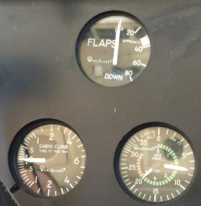
∆P is simply the difference between inside and outside pressure, cabin pressure vs. ambient pressure, ∆P = PCABIN – PAMBIENT. (PAMBIENT = PSTATIC. Same thing.) It is obvious where the ∆P gauge gets the PCABIN part of the equation…it is the same pressure that is used by the gauge for its cabin altitude display. But what about PAMBIENT? Where does this gauge measure outside pressure?
Of course, it must have a line connected to one of the airplane’s static sources. We have three of them in most King Airs: Pilot’s Normal static system, Copilot’s Normal static system, and Pilot’s Alternate static system. (Early model King Airs had only one Normal system that fed both Pilot and Copilot instruments and the Alternate system also fed into both sides. Check the static ports on the sides of the aft fuselage. Got two per side? That’s the newer and more plentiful system. Got only one per side? You have the original, older, system.)
The ∆P gauge ties into the Alternate Static System. You may recall from previous training that the alternate static air line goes from the selector lever – usually, but not always, on the cockpit’s right sidewall – to and through the aft pressure bulkhead. It terminates there, just above the “hellhole” access door on the bottom of the fuselage. The end of this line is quite close to the right side of the fuselage, an inch or so above the bottom skin. It is easily seen through an open hellhole door.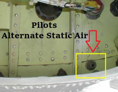
Because the selector valve in the cockpit sits higher than the pressure bulkhead hole, the static air line generally flows downhill from forward to aft so it has no moisture drain provided. Any condensation should drain automatically by flowing downhill. (That petcock drain you find behind the small, upholstered, access panel on the right side of the baggage compartment is a drain for the Outflow Valve’s control line, not a static line drain.)
Consider two malfunction scenarios involving the ∆P gauge. First, suppose the gauge reads low in cruise. Instead of seeing close to 6.5 psid in your lovely 250 you are seeing about 2.7 psid. (Any number lower than 6.5 would be OK for my example. 2.7 is just the number I picked.) Before you conclude that your pressurization system is weak perhaps due to excessive leaks and/or weak Flow Packs, look carefully at the combination gauge again. What Cabin Altitude is being displayed? If you’re cruising at, say, FL270 and only have 2.7 psid, your cabin must be quite high, in the vicinity of 19,000 feet. If that is indeed what you see – and the red Cabin Altitude warning annunciator is on and the oxygen masks deployed a while ago! – then you surely have a major pressurization problem.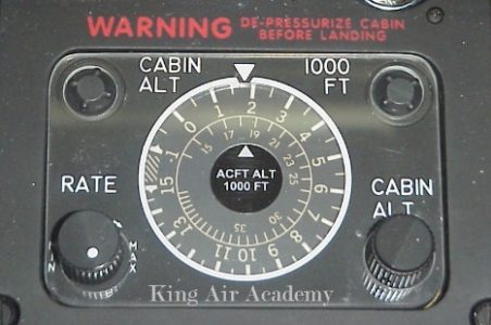
But what if the cabin altitude is right where it should be, close to 7,000 feet? Why is ∆P so low when the cabin pressure is not all that low? The answer must be that our PAMBIENT value is incorrect, is too high. And what could cause that? A leak in the alternate static air line between the selector lever and the aft pressure bulkhead that is allowing some of our cabin air to leak into the static line. So now the static line is no longer correctly reading outside, ambient, pressure but instead is feeling a higher pressure, somewhere between Ambient and Cabin.
Pop Quiz: What would happen to the pilot’s airspeed, altimeter, and vertical speed readings of you selected Alternate Air now? Answer: They’d all go down like a dropped anvil!
Here’s the second malfunction scenario, and a much rarer one: All has been fine until the descent begins. Now you observe the ∆P gauge is exceeding the redline value! The more you descend, the greater the ∆P becomes. Dang! We’re going to blow the door off!
Again, slow down and check the actual cabin altitude. Is it “normal,” somewhere between what it was in cruise and where it is going to be for your landing? If so, then ∆P cannot be too high. You merely have a ∆P gauge problem. Since ∆P = PCABIN – PAMBIENT and we are relatively sure that PCABIN is normal, the only way that ∆P can be high is for PAMBIENT to be incorrectly low.
The likely cause of this malfunction – albeit extremely unusual – is that somehow up at altitude something (ice?) clogged the alternate static air line. The low ambient pressure that it was sensing in cruise is now trapped and is not changing, not increasing as it should in a normal descent. Relax. Once the ice melts the ∆P reading should return to normal operation.
The takeaway here? The ∆P gauge not only reads Differential Pressure but can give us an idea of the correctness of our Alternate Static air system even before the selector lever has been moved to send that alternate air to our flight instruments.
The Maddening Story of BE-200 Takeoff Data
I recently bought a POH for the latest B200GTi model to satisfy my curiosity about the probable changes that would be shown in its takeoff data, as compared to its less powerful B200 and straight 200 predecessors. Wow, was I disappointed! Read on to hear the sad but true story of the development of this data and why, on paper, the PT6A-52-powered GTi of 2010 has identical performance as the PT6A-41-powered 200 of 1974. Thirty-six years of product improvement and evolution yet not one iota’s worth of takeoff data change…it’s maddening.
As many of my readers know, I worked at the Beechcraft Training Center in Wichita in the’70s, was the first instructor on the model 200, and consequently have a degree of historical perspective on the development process. The 200 was originally called, in-house at Beech, the model 101, since it had the identical cabin size as the 100-series. However, with so many rather large changes – more power, bigger propellers, more fuel, the T-tail, improved cockpit layout, and improved maintenance access, to name a few – it soon became obvious that this was not just another minor evolutionary change to the King Air family tree. So the name that Mrs. Olive Ann Beech herself selected – the Super King Air 200 – was not quite as corny as it seemed initially to lots of us Beechcrafters back in the early ’70s. Compared to the A100, the 200 really was super!
Beech now had a King Air with enough power that it could lose an engine during the takeoff ground roll and actually be capable of lifting off, accelerating, and retracting the landing gear while climbing, and all while at the maximum gross takeoff weight limit of 12,500 pounds. (Realize that the highest-performing big-cabin King Air prior to this time was the rather anemic A100. As for the smaller-cabin models, the impressive E90 had just been certified but F90s and various versions of the PT6A-21-powered C90s had not yet hit the scene.) Of course, this singleengine takeoff climb could not occur at every combination of field elevation and OAT but at least at sea level there was no OAT hot enough to prevent this capability, and yet still be below the OAT operating limit of ISA + 37ºC. (At sea level, that’s 52ºC or 126ºF!)
Every prior King Air model, going all the way back to LJ-1, the first “65-90,” or straight 90, had Airplane Flight Manual data that not only showed the FAA-required info about two-engine takeoffs but also contained some nice-to-know, non-required, data such as Accelerate-Stop Distance. There was also a chart entitled “Single Engine Takeoff Distance.” When one read carefully the associated conditions upon which this chart was based, it became obvious that the airplane did not become “Single Engine” until near Decision Speed (V1). In other words, this was the other option when an engine failure was recognized right at V1. The first option was to pull power and stop, as presented in the Accelerate-Stop Distance (A-S) chart. The second option, if it existed at all, was to continue the takeoff on the remaining engine, what was now being presented as Single Engine Takeoff Distance.
(It may be apocryphal, but I was told by an old hand at Beech that the chart’s title was changed from Single Engine Takeoff Distance to Accelerate-Go Distance (A-G) after some Bozo ran off the end of a runway trying to indeed make a single-engine takeoff…starting from a dead stop.)
Although this Accelerate-Go chart has existed since Day One for all King Airs, in most cases it was discovered to be rather meaningless. Unless the airplane was extremely light, the air was cool, and the runway was long, A-G could not be achieved.
Surprising? Not really. You must keep in mind the performance standards of the sixties and early seventies. Could a Queen Air 80 lose one at rotation and keep going? How about a Cessna 310? Want to do it in an Aztec or Navajo? Yes, I remember when Ted Smith had one of his prototype Commanders flown from Oklahoma City to Washington, D.C, with one of its propellers stowed in the baggage compartment – A most impressive publicity-grabber! – but it was impressive mainly because it was so unheard of in that day and age.
Realistically, using the mindset and the performance of the day, if an engine quit on these light twins prior to reaching VYSE with the gear retracted, the outcome was always stopping, never going. (Just like today in most light twins, eh?)
The marketing efforts designed to help the King Air sales team do their job spent little time on discussing bad things such as engine failures on takeoff. It was much better to talk about cabin comfort, pressurization, turbine engine smoothness and reliability, etc. If – and that was a big IF – the prospective King Air buyer inquired about what resulted if an engine shed a few turbine blades on the runway, the salesperson’s response was to talk only about Accelerate-Stop distance, and that number was always quite short, quite competitive.
Let’s return now to the exciting days of 1972, ’73, and ’74 when the two prototype 200s (BB-1 and BB-2) were undergoing flight testing and FAA certification. While that was going on at Beech field in Wichita, guess what was happening across town? (Bring up the theme music from Jaws in the background.) The Cessna C-I-T-A-T-I-O-N was also being certified! Obviously the Super King Air 200 and the Citation 500 were and are very different airplanes. Yet, they were in intense head-to-head competition for sales, being priced very similarly. Cessna was going for Transport Category, FAR Part 25, large airplane certification. Beech was sticking with FAR Part 23, avoiding a lot of the extra requirements of the “big guy” rules. Whereas the Citation, for example, had to demonstrate successful one-engine-inoperative takeoff data, as well as pass the Transport Category icing tests, Beech did not. “Well,” said the Beech sales staff, “we’re going to be at a disadvantage when the Cessna salespeople can say they’re just like a Boeing, but we cannot!” With this type of thinking in mind, Beech made the decision (1) to conduct icing tests using the Part 25 requirements, and (2) to test and publish an entire set of takeoff data that would comply with all FAR Part 25 rules. They made these decisions voluntarily, doing so to be more competitive with the Citation, even though there was no FAA requirement to do so.
The icing certification outcome – heck, for that matter, nearly everything! – came out very, very, well on the 200. Few pilots who have had the pleasure of operating this excellent aircraft have many complaints about it. Certainly a 2010 B200GTi has a whole batch of nice improvements compared to a 1974 model, but they are both absolutely excellent flying machines.
Unfortunately, that excellence does not carry over into how their Part 25 takeoff performance charts were created. Allow me to explain.
Remember that I have presented why Accelerate-Stop was so much more-emphasized and morediscussed for so many years than Accelerate-Go. To review: We could always stop; to go was often impossible.
How does one make A-S numbers as short as possible, both for safety and to look good on paper? Having a lot of power to quickly accelerate to V1 helps, as do good brakes for strong stopping. What else? The choice of V1 speed. That single factor is huge!
To state the obvious, if V1 were 30 knots, getting to that low speed and then getting fully stopped would be a breeze and require very little distance. Not much energy would need to be gained; not much energy would need to be lost. On the other hand, if V1 were 130 knots, getting to it would require lots of time and distance (not to mention the difficulty in forcing the airplane to remain on the runway when so much lift is being generated) and getting stopped, likewise, would require a lot of distance.
Since Beech had decided to comply with the FAR 25 rules that existed, it was found that the lowest V1 speed permitted was 5% above Air Minimum Control Speed: 1.05 x VMCA. With flaps up, taking the VMCA of 91 KCAS, multiplying by the 5% factor to get 95.55 CAS, then converting that back to IAS using the CAS/IAS correction chart that applies during the takeoff ground run, the lowest V1 Beech could use was 95 KIAS. When Approach flaps were used for takeoff, the number, calculated the same way, dropped to 94 KIAS.
“So far, so good,” it seemed. “Not only do we have about 1,700 horsepower to accelerate to V1 (850 per side), but since we are only doing this voluntarily, without FAA oversight requirement, let’s not only use maximum braking to get stopped but let’s also throw in full single-engine reverse right down to zero speed! Oh, for sure, we’ll blow a few main tires doing the testing and erode the heck out of the propeller blades staying in Reverse for so long, but the number is going to be very, very, short! Take that, Citation 500!” The sun shone brightly and life was good at Beech Field…for a while.
Now it was time to look at the other side of the equation: Accelerate-Go. We are required to use the same V1 for stopping and going. But what do the FAA rules say about V2, Takeoff Safety Speed? Although I am simplifying a bit here – because there is more than one criterion – the rule that was found to be the limiting factor for the model 200 King Air is that V2 must be at least 20% above power-off stall speed in the takeoff configuration: V2 ≥ 1.2 x VS. Doing the math and converting from calibrated back to indicated airspeed, the maximum gross weight numbers for the 200 become 121 KIAS, clean, and 106 KIAS with flaps at Approach.
I have no complaints or reservations whatsoever with these V2 speeds, 121 and 106. They meet the FAA requirements and provide plenty of stall protection and reasonable climb performance. But those 95 and 94 knot V1 speeds? They are bad, bad, bad! I hope I can convince you to consider not using them in nearly 100% of your takeoffs. Read on.
Let’s do a little mental imaging exercise together and step through the two opposite scenarios we have available to us after recognizing an engine failure right at Decision Speed. For simplicity, we’ll use the classic Sea Level, standard temperature (15ºC), maximum weight, no wind, paved, level dry runway conditions. We lock the brakes, rev up to the torque limit (2,230 ft-lbs) at maximum propeller speed (2,000 RPM), release the brakes, and rocket down the runway. Considering the stopping choice first, right at 95 KIAS we simultaneously pull both power levers to Idle and get on the brakes aggressively. Immediately, we continue with lifting the good engine’s power lever over the Idle gate (and the Ground Fine gate, too, for later models, after 1992) and holding it all the way back at maximum Reverse while we use “maximum braking without skidding the tires.”
There are three things here to consider: First, how do you always know which power lever to lift and pull back into Reverse? Could you always with 100% accuracy realize which engine it was that stopped producing power? I don’t think I could! So what I’d do is lift both power levers and pull them both fully back. Now what? Well, depending on what the dead engine’s propeller is doing, I may get some reverse blade angle but I also may find myself fighting cable resistance as I ask for the blade to go into reverse but insufficient prop dome oil pressure exists for that to occur. If one of the two power levers binds up as I try to get it fully back, then I’ll not force it but merely continue with what I now know is the operative engine.
Second, did you remember to push the control wheel fully forward with your left hand at the same time the right hand pulled power to idle and reverse and the feet got on the brakes? You did? Great! You didn’t? Uh-oh! That explains why you are about ten feet above the runway now!
This unexpected liftoff positively blew my mind when I first saw it demonstrated! Let me tell you about it. Bud Francis, the chief test pilot on the 200 certification program, took three or four of us Beechcraft Training Center instructor/pilots out in BB-1 in early 1974 to show us for the first time what this new model was all about. The extra power and climb performance were immediately obvious. The T-tail allowed flaps to be extended and retracted with very little trim requirement. The long wing was cool – nearly ten feet longer than the A100 – and it was a gentle giant in the landing flare compared to the fall-out-of-the-sky 100. That extra wing length was due both to a longer wingtip extension – like that on a Baron compared to Bonanza, or on a B90 compared to an A90 – as well as to a 25-inch per side wider wing center section.
The center section was widened to allow larger diameter propellers to be installed and to give a great deal more propeller-tip-to-fuselage clearance to make the cabin quieter. If the existing engine mounts had been used, this bigger prop would have had too little tip-to-ground clearance, so a new mount was designed and fabricated which lifted the propeller shaft nearly four inches higher than it had been in previous models. The next time you are on a ramp, stand well to the side of a King Air and look carefully down the lateral axis toward the fuselage. Make note of where the center of the propeller lies relative to the wing chord. Compare what you see on any 90- or 100-series model to what you observe on a 200- or 300-series. It becomes quite obvious that the thrust centerline on the 200-type is much, much, higher than on the earlier ones.
Now back to our flight training in BB-1. We various instructors were rotating into and out of the left seat as Bud led us through the various demonstrations he wanted us to see. The stark cabin in this prototype had no interior panels and the seats were all forward-facing with no cabin partitions so the observers had a good view of what was happening. On the 13,500 feet long, 300 feet wide runway at Salina, Kansas, we had been making some takeoffs, landings, and touchand-goes. As we taxied back and lined up in position for our next demonstration, Bud asked the left seat trainee to make a totally normal no-flap takeoff that would be aborted at 95 knots. He even reached over and pulled the landing gear control circuit breaker since we were stopping, not going, this time…a neat little safety gimmick I learned from him and that I use whenever I practice aborted takeoffs with a student. (By pulling that CB, there is no chance whatsoever the gear will get retracted even if the handle gets bumped while the squat switch is in the Air position because of a bumpy runway.) However, Bud instructed, he wanted the student to do two things differently from normal: (1) Keep his left hand in his lap, don’t touch the control wheel at all. (2) Only pull the power levers to the Idle stop during the abort, don’t use any Beta or Reverse.
We accelerated down the runway until Bud yelled “Abort!” at about 95. The student closed the power levers as directed. It would be fun to have had a hidden camera that could have caught the wide-eyed, open-mouthed, amazement of us observers! Damn! We were flying! The crazy machine had rotated itself and lifted off! What the …??!! Ever calm Bud – who of course knew what was coming – merely put in one notch of flaps, nosed over, and made a lovely touchdown with thousands and thousands of feet of runway to spare. As we taxied back, he explained what had just happened. That four-inch higher thrust line means that the wing is always being rotated in a nose-down direction when thrust is added and, vice-versa, rotated nose-up when thrust is negative. The normal horizontal stabilizer’s angle-of-incidence and the takeoff trim setting serve to nullify this rotation tendency for the most part during acceleration. As we had just experienced, when those big props immediately change from pulling to pushing, it causes enough nose-up rotation, enough increase in the wing’s angle-of-attack, to create liftoff!
Bud Francis was a wonderfully sharp test pilot and experienced aviator and expressed to all of us at the time his belief that not enough emphasis was being placed on positively pushing the wheel forward during aborted takeoffs. Although he felt this was important in virtually all airplanes, regardless of the model, it was critical in the 200! I have tried to teach this to my students but am not sure that I have always been successful. If you have not heard of this phenomenon before, hear it now. It should be more thoroughly discussed in the associated conditions of the POH’s Accelerate-Stop chart, but it earns nary a mention.
The third thing to consider about the aborted takeoff procedure – after realizing you’ll need to reverse both power levers in most cases since it won’t always be obvious which engine is inoperative, and after remembering to push the wheel fully forward with the left hand – is that pesky little item of directional control, or staying on the runway. It is a bit eye-opening to practice single-engine reverse in a BE-200 for the first time. When we at the Beechcraft Training Center started checking pilots out in the new 200 back in late 1974 and after, it was agreed that we had better include single-engine reverse practice drills in our curriculum since the aborted takeoff data was predicated on it. Uh-oh. We discovered both good news and bad news. The good news was that we found pilots could make many takeoffs and landings in a 200 with one main tire having a fifty-cent-piece-size hole scraped in it and never know it! The airplane taxied, landed and tookoff just fine on only one main tire. The bad news was that we rarely ever came back from a flight that included single-engine reverse practice without discovering a blown – and always an outboard, never an inboard – main tire! What to do?
A meeting of instructors was held. Although the obvious – “Don’t practice single-engine reverse with students anymore!” – was stated as an option, it was rejected since it was felt we were compelled to teach what the POH contained. What was finally suggested and agreed upon was the adoption of an Instructor Pilot (IP) technique that would always be followed during this training. The IP technique involved three separate steps. First, we would brief the students to keep their heels on the floor and to avoid touching the brakes. (In a real life abort, of course brakes will be used and a tire will almost assuredly be blown. So be it. But for training, brakes had to go.) Second, without even mentioning what was being done, the IP would always raise the flaps to the full Up position. During a no-flap takeoff, of course this was already the case. But if an Approach flap takeoff was being made prior to the abort, or if single-engine reverse was being utilized on roll-out following a simulated single-engine landing, up the flaps would come. Third – and definitely the most novel idea to most of us – was to emphasize “steering with the control wheel.” For example, if the student was fighting a tendency to deviate to the left, due to left propeller reversing, then we would encourage him/her to take the wheel and turn it fully to the right: “Steer to the right with the wheel.”
This steering with the wheel improved the situation not because of the difference in Up versus Down aileron drag. (In fact, that minor effect would be working against us!) Instead, it was because doing this as soon as reverse was selected, still at a relatively high speed, allowed the ailerons to help lift up on the good engine’s side and to press down on the dead engine’s side. You see, contributing to the swerve toward the good engine was not only the reverse thrust on that side but also the fact that that side’s wing was more deeply stalled since much of the airflow was being blocked or deflected forward by the reversing propeller. Since less lift was being generated, the main tires on that good side were carrying more of the airplane’s weight than the tires on the other side, the side that was still generating quite a bit of lift since the bad propeller was in feather, or simulated so. That extra weight on the main tires was another factor that was pulling the airplane toward the good engine’s side.
As soon as that IP technique became ingrained – no brakes, retract the flaps, steer with the wheel in the direction you want to go – the cases of blown tires immediately ceased!
Now we’ll return to where this article was going before we went into this important side discussion: We were doing a mental imaging exercise of aborting a SL, flaps up, takeoff at 95 knots. Now you know to push forward on the wheel, be as gentle on the brakes as distance allows, steer with the wheel, and be prepared to possibly experience resistance on one power lever as you go into Reverse as needed.
Now let’s do the other mental exercise: Going, not Stopping. This time, after recognizing an engine failure at 95 KIAS, we will continue and complete a successful single-engine takeoff up to 35 feet above the runway. (By the way, does the Boeing company have better FAA lobbyists than the General Aviation manufacturers? How come Part 25 certification gets to use a 35-foot tree while Part 23 continues to grow ’em 50 feet tall? Hmmmm?)
Not that the FAA Part 25 takeoff rules require it – they don’t – but in the case of the 200 and many other King Air models, Beech chooses to make V1 equal to VR. What exactly is VR, Rotation Speed? It is the speed at which the nose tire leaves the runway. Do you remember all of that nose-down rotating moment I described to you that the high thrust line is providing during the 200’s takeoff roll? I am very convinced that not one 200 pilot out of twenty uses a flap-up VR of 95 knots, even though they think they are! Most pilots wait and don’t really start pulling the wheel back until about 95. In that case, guess when the nose starts up. It won’t be until another ten knots or so has been gained. I don’t often point this out to my students because – and to where this article is leading – I hope I can convince you that using a 95 KIAS V1 is a horrid idea in most situations. Nevertheless, it is apparent to me that few pilots make rotation occur at the designated speed.
Unless the control wheel is pulled to a half-way-back, neutral, location no later than 80 knots, there is zero chance of making a smooth rotation. Instead, at higher speeds near V1, the elevators cannot resist the nose-down moment of the propeller thrust until a lot of elevator travel is achieved and then the wheel is like an On-Off switch. Wham! Up comes the nose and we overrotate and trigger the stall horn. (Been there, done that, haven’t you?) So I hope you’ve learned to seek that elevator-neutral point fairly early during the takeoff run and add just enough additional back pressure to make the wing’s angle-of-attack ease into the positive range right at the VR you are targeting. It takes a little practice but it is ever-so-satisfying when done correctly.
Just as that nose is smoothly lifting at 95 KIAS, we realize that something feels mighty wrong and that a lot of rudder is needed to keep tracking straight, but we proceed to continue…doing the Accelerate-Go thing. What comes next? Gear up!
Many of you know my preaching about using our “Four Friends” whenever in doubt: Power, Props, Flaps, and Gear. In this scenario, Power? Already at takeoff. Props? Already full forward at 2,000 RPM. Flaps? Already up. Gear? Yes, now’s the time.)
Now it’s time to do the Identify/Verify/Feather steps, isn’t it? No. Why not? Because the optional autofeather system has already activated and the propeller blades, if not already fully in feather, soon will be.
“But wait, autofeather is an option in many 200s. What if my airplane doesn’t have it or it’s on the MEL’s inop list today?” Sorry. In these cases, you cannot get any usable data from the POH’s Accelerate-Go charts. Since these charts were never FAA-required not FAA-blessed, remember that Beech basically could do whatever they wished, even though they wished to meet the intent of FAR Part 25. Knowing that immediate feathering of the dead engine’s windmilling propeller is a critical step in the A-G procedure, they opted to conduct all of these tests in an autofeather-equipped plane and specify in the chart’s associated conditions that autofeather was armed throughout the procedure. Like I said, if you don’t have it, too bad. If you must feather yourself today, I don’t even want to think about how long a distance this procedure will require!
So now we are off the runway, the propeller is being automatically feathered and the gear is being retracted. What airspeed are we striving to attain? Before we reach 35 feet and climb mostly out of ground effect, we need to be at V2 to have a safe airspeed margin above stall speed. We recognized the engine failure just as the nose was lifting at 95 knots, the main tires left the runway shortly thereafter – for a while, Beech actually listed the lift-off speed as 101, but then decided this was an extraneous and unnecessary figure since when it happened after rotation was impossible for the pilot to control with any degree of accuracy – and now we are accelerating to 121 knots while climbing the rest of the 35 feet.
Do you have any idea of how meager this initial climb will be? Under the conditions of gear not yet fully up, propeller not yet fully feathered, and the pitch attitude kept low enough so that we won’t reach 121 until 35 feet…it is going to be difficult, to say the least. That is why there is no semblance whatsoever of a “Balanced Field” according to the takeoff charts for a 200.
Nowhere in FAR Part 25 takeoff rules does it state that Accelerate-Stop and Accelerate-Go distances must be equal, be balanced. But the concept of a Balanced Field has been recognized for ages as the “optimum” way to go. Since the FARs do say that both the A-S and A-G procedures be accomplished safely in available distances, it does little good to have a Stopping distance significantly longer or significantly shorter than the Going distance or vice-versa. Since both distances must be met, we always must have the longer distance available.
For example, if it takes 3,000 feet to comply with A-S requirements but 4,000 feet to comply with A-G, we must have at least 4,000 feet of runway. If we stop, doing it perfectly, we will leave 1,000 feet of the least runway unused. Alternately, in another set of conditions, if it requires 5,000 feet to A-S but a mere 3,500 feet to A-G, then we must use a 5,000 feet or longer runway. If we stop on the minimum length runway we come to a halt with the nose tire teetering on the runway lip but if we go we will be well above 35 feet as we clear the trees at the runway’s departure end.
I am happy to notice that reference to Balanced Field Length seems to be fading away, since it was never a regulatory requirement. Instead – for example, in the King Air 350 (B300) data – a distance called “Takeoff Field Length” is presented. Based on the conditions specified – weight, altitude, OAT, wind, etc. – and doing everything right, by the book, we know that if we abort at V1 we can safely stop within this specified distance and that if we continue we will reach at least 35 feet and V2 within that distance. Can we tell via these charts which will require the longer distance, Stopping or Going? No. All we know is that both can be accomplished within a distance that will not exceed Takeoff Field Length.
When the Beech 200 development team decided to use a V1 of 95 and a V2 of 121, the die was cast. Any chance at minimizing field length requirements by having the two distances “meet in the middle” was lost. Although the numbers with Approach flaps – 94 and 106 – made the Going distance more reasonable since there was “only” a 12-knot acceleration required (instead of the 26-knot gap between 95 and 121) still, the Stopping and Going distances always favored a shorter Stop and a longer Go.
Remember why Beech liked this dichotomy: Shorter Accelerate-Stop distances sold airplanes, so they thought, and few buyers even considered asking about Accelerate-Go.
Ah, but those mean ol’ Cessna salespeople! Why, they had the nerve to tell some of the prospective buyers that our SL, “Balanced Field Length” was over 6,300 feet! “Well, yeah, that was the flaps up A-G distance, but, come on, our A-S is only 3,400 feet! And how often do turbine engines ever fail on takeoff anyway? And, isn’t this walk-up airstair door impressive?
Now where were we? Have I talked about our financing plans yet?”
It seemed obvious to many of us – both inside and outside of Beech – that this over-riding desire to minimize A-S was very misguided and left us at a large disadvantage, both in selling against the Citation and, more importantly, in really maximizing our takeoff safety considerations.
Well, hallelujah! In 1978 when the F90 appeared, the V1 speed was increased and hence its distances became much more balanced. In 1984, with the appearance of the model 300, and now with the FAA looking over Beech’s shoulder as they certified this no-longer-light twin, again the speeds reflected more logical thinking. The 300’s maximum takeoff weight is 14,000 pounds. Although that is 1,500 pounds more than the 200’s maximum weight, stall speed actually decreased slightly due to an enlarged and reshaped leading edge on the wing’s center section. V2, still calculated as 1.2 times stall speed, is now 120 KIAS, a whole one knot less than the 200’s 121. But V1? It is 112, not 95! So now, even with 200 more horsepower in the remaining engine that has to accelerate us from V1 to V2, we are expected to gain a mere 8 knots, not that fearsome 26-knot figure of the 200. Wow! The A-S and A-G numbers got a whole lot more balanced! Further improvements were forthcoming with the 350, too.
In 1981, the B200 started being phased into production as the straight 200 was phasing out. The major difference between the models was an engine change from the PT6A-41 to the PT6A-42. Although both engines were rated at the identical 850 SHP at Sea Level, the -42’s compressor and hot section components were optimized to produce more power in thinner air. Consequently, the B200 averages about 10 knots faster in cruise and it rarely ever cannot use its full 850 SHP for takeoff, even out of Aspen in the summer, very unlike the -41-powered straight 200.
Surprisingly, the takeoff data was not changed! Instead of re-testing using the -42 engines, Beech merely copied the straight 200 data into the B200 POH. Cruise performance was changed, yes. Takeoff and landing data, no. Realize that when a manufacturer or a modifier makes a product change, there is no FAA requirement to prove an improvement so long as it can be shown that no performance degradation occurred and no claim for improvement is made.
I have always been disappointed that charts are not available for B200 operators to truly gauge their “high and hot” takeoff performance. I totally agree that the straight 200 is no slouch when it comes to takeoffs, but I know that the B200 is even better when the field conditions get challenging.
Ah, now comes the B200GT, with the marvelously strong PT6A-52 powerplants. Wow! More than 300 knots top cruise speed! Nearly 35 years have passed since Beech made those crazy 200 takeoff charts using the unconscionably low 95-knot V1. “At long last,” I say to myself, “I know we’ll see some reasonable takeoff data reflecting the tremendous extra high-and-hot engine power as well as the 300/350 type approach to more balanced numbers.”
I find that I am mistaken. Once again, the takeoff data in the GT is merely a duplication of the
200 data from the early 1970s using -41 engines. How disappointing. How sad. How cheap. Yes,
I know the economy is in the tank and manufacturers need to carefully control every penny. By not doing any new takeoff testing, I am sure Hawker-Beechcraft saved a bundle. Was it worth it? I hope they think so. In my view, as I said, it’s maddening.
I can grant Hawker-Beechcraft this much: They have erred on the side of safety. By never publishing data that utilizes the extra power available from –42s and –52s for high and hot conditions, the data presented is extremely conservative. Speaking for myself, however, I’d really like to see how an extra 25% power would change the numbers at Aspen!
There are really two separate issues that this article is addressing. The first is that even the latest B200GTs use the takeoff data that was developed using the 200’s original -41s. The second is that using a V1 that is within 5% of VMCA and is greatly below V2 makes almost no sense at all.
Wait, there is one situation in which the gross imbalance between a shorter A-S versus a much longer A-G does indeed make sense. KAVX, Avalon, California, the Airport In The Sky on Catalina Island, comes to mind. On that short, carrier-deck runway created from carved-off mountain tops, being able to stop without sliding over the end and down the mountain is a very good thing. If we just barely crawl into the sky just pass VMCA when the runway disappears, as we continue with an engine failure experienced right at our low decision speed, I have no tree to hit for the next 26 miles heading east…or over 2,000 miles, heading west! Heck, instead of climbing as I accelerate to V2, I could descend 500 feet and still be more than 1,000 feet above the ocean!
Although I bet there are a few other Catalina-type airports in the world, they are by far the exception to the rule. As someone once commented to me, “Oftentimes the reason the runway is not longer is because there’s something big and immovable at the end.”
So where do we operators of 200s, B200s, and B200GTs stand? What takeoff numbers do we use if not Beech’s own?
There is an easy answer to these questions for airplanes that have the full Raisbeck Engineering performance enhancement package. As some of you know, the Raisbeck crew did actual flight testing to derive true solid Takeoff Field Length numbers that apply to the 200-series with their enhancements. The POH Supplement is quite a large document – it even comes in its own binder – and contains a wealth of changed, improved, data.
For the rest of us, we’re on our own. It is with reluctance that I suggest a method of V1 calculation that has no support in the POH. Based on the lengthy dissertation presented thus far, however, I hope that you realize I have a fragment of solid ground upon which to base my stance. The method I am about to suggest comes up with V1 values similar to, although not identical to, those used in the model 300. A decision speed that is correct in one situation (i.e., a takeoff from Salina’s 13,500 foot-long runway) is not correct in all other situations (i.e., Catalina Island).
Here is my recommendation for a “typical” situation: For a Flaps Up takeoff, make V1 equal to V2 minus 10. If Approach Flaps are used, make V1 equal to the new V2 minus 5. With a clean wing, accelerating only 10 knots from V1 to V2 is a realistic proposition. With the extra drag coefficient that the flaps provide, now we only have a 5 knot increase to achieve. To make it crystal clear, here is a table of the suggested V1 and V2 numbers:
|
WEIGHT
|
FLAPS APR |
FLAPS UP |
||
|
V1 |
V2 |
V1 |
V2 |
|
|
12,500 |
101 |
106 |
111 |
121 |
|
12,000 |
100 |
105 |
109 |
119 |
|
11,000 |
98 |
103 |
105 |
115 |
|
10,000 |
96 |
101 |
101 |
111 |
|
9,000 |
94 |
99 |
98 |
108 |
These numbers cannot be perfect in all situations, but I am totally sure that they will give you an overall higher level of safety than the use of the POH’s blanket 95 and 94 knot V1 figures. Now remember, as I wrote before, you cannot wait to start the wheel back until you reach V1 and expect to have V1 and VR the same, as you desire. To make this your actual rotation speed, the speed at which that nose tire lifts off, be sure to have the elevators in neutral much earlier.
In conclusion, remember that the BE-200-series, not withstanding all of their wonderful attributes, are still light twins. Any reference to engine failure on takeoff is not required by FARs. Any data pertaining to such is not FAA-approved. On the other hand, unlike the anemic 150 HP Piper Apache, the King Air 200 does indeed have some single-engine capabilities that are quite impressive, including its ability to lose one on the runway and make a successful departure in many situations. Understand the rationale Beech used in creating the 200’s takeoff data and then decide how you wish to conduct your own takeoff planning. Fly safely!